April 24, 2015
by Andrey Filippov
Working with the DDR3 Memory interface I was not able to avoid the temptation to investigate more the very useful feature of the modern FPGA devices – individually programmed input/output delay elements on all (or at least many) of its pins. This is needed to both prepare to increase the memory clock frequency and to be able to individually adjust the timing on other pads, such as the sensor ports, especially when switching from the parallel to high speed serial interface of the modern image sensors.
Xilinx Zynq device we are using has both input and output delays on all low-voltage pins used for the memory interface in the camera, but only input ones on the higher voltage range I/O banks. Luckily enough image sensors connected to these banks need just that – data rate to the sensors is much lower than the rate of the data they generate and send to the FPGA.
(more…)
September 10, 2014
by Andrey Filippov
We just tested two samples of Evetar N123B05425W lens that is very similar to Sunex DSL945D described in the previous post.
Lens Specifications
|
Sunex DSL945D |
Evetar N123B05425W |
|---|
| Focal length |
5.5mm |
5.4mm |
| F# |
1/2.5 |
1/2.5 |
| IR cutoff filter |
yes |
yes |
| Lens mount |
M12 |
M12 |
| image format |
1/2.3 |
1/2.3 |
| Recommended sensor resolution |
10Mpix |
10MPix |
July 26, 2014
by Andrey Filippov
We were measuring lens performance since we’ve got involved in the optical issues of the camera design. There are several blog posts about it starting with "Elphel Eyesis camera optics and lens focus adjustment". Since then we improved methods of measuring Point Spread Function (PSF) of the lenses over the full field of view using the target pattern modified from the standard checkerboard type have better spatial frequency coverage. Now we use a large (3m x 7m) pattern for the lens testing, sensor front end (SFE) alignment, camera distortion calibration and aberration measurement/correction for Eyesis series cameras.
Fig.1 PSF measured over the sensor FOV – composite image of the individual 32×32 pixel kernels
So far lens testing was performed for just two purposes – select the best quality lenses (we use approximately half of the lenses we receive) and to precisely adjust the sensor position and tilt to achieve the best resolution over the full field of view. It was sufficient for our purposes, but as we are now involved in the custom lens design it became more important to process the raw PSF data and convert it to lens parameters that we can compare against the simulated achieved during the lens design process. Such technology will also help us to fine-tune the new lens design requirements and optimization goals.
The starting point was the set of the PSF arrays calculated using images acquired from the the pattern while scanning over the range of distances from the lens to the sensor in small increments as illustrated on the animated GIF image Fig.1. The sensor surface was not aligned to be perpendicular to the optical axis of the lens before the measurement -each lens and even sensor chip has slight variations of the tilt and it is dealt with during processing of the data (and during the final alignment of the sensor during production, of course). The PSF measurement based on the repetitive pattern gives sub-pixel resolution (1.1μm in our case with 2.2μm Bayer mosaic pixel period – 4:1 up-sampled for red and blue in each direction), but there is a limit on the PSF width that the particular setup can handle. Too far out-of-focus and the pattern can not be reliably detected. That causes some artifacts on the animations made of the raw data, these PSF samples are filtered during further processing. In the end we are interested in lens performance when it is almost in perfect focus, so scanning too far away does not provide much of the practical value anyway.
(more…)
June 20, 2014
by Andrey Filippov
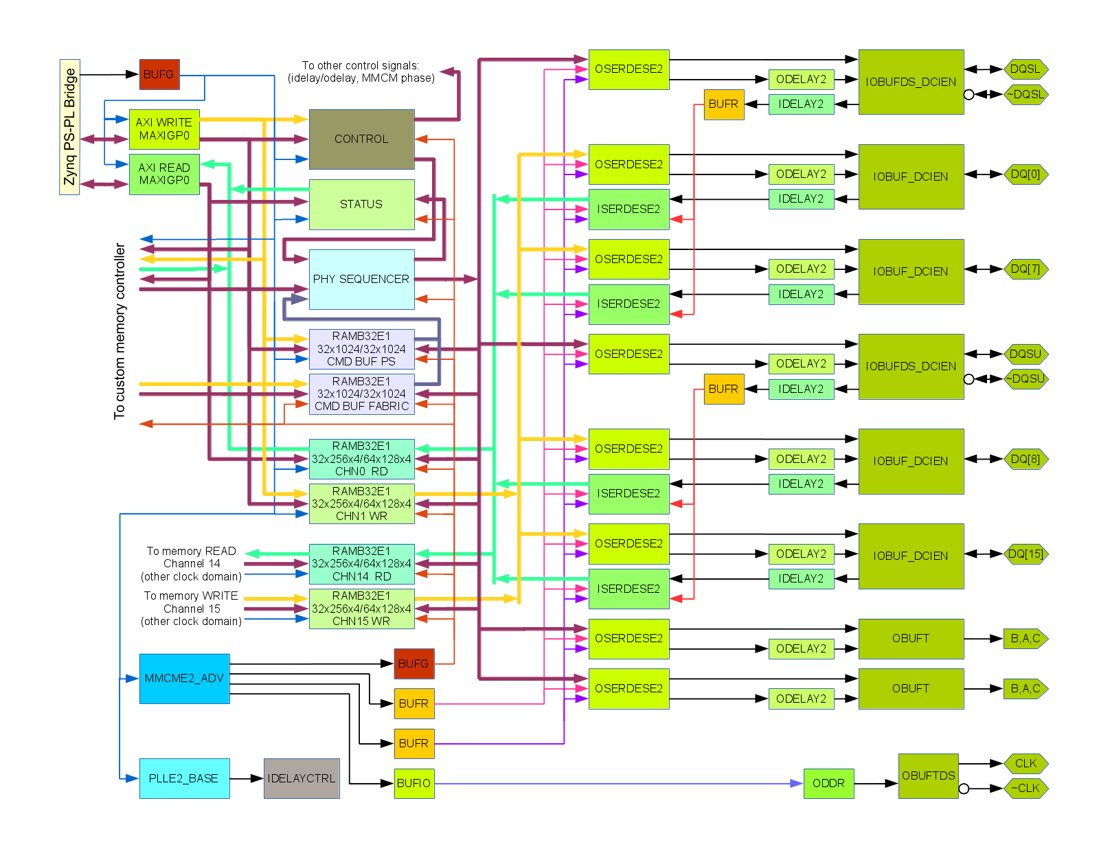
External memory controller is an important part of many FPGA-centered designs, it is true for Elphel cameras too. When I was working on the board design for
NC393 I tried to
verify inteface pinout using the code output from the MIG (Memory Interface Generator) module. I was planning to use MIG code as a reference design and customize it for application in the camera, adding more functionality to our previous designs. Memory interface is a rather intimate part of the design where FPGA approach can shine it all its glory – advance knowledge of the types of needed memory transactions (in contrast with the general CPU system memory) helps to increase performance by planning bank and address sequences, crafting memory mapping to utilize close to 100% of the bus bandwidth.
(more…)
December 17, 2013
by Andrey Filippov
The software used in the previous Elphel cameras was based on the GNU/Linux distribution supported By Axis Communications for their ETRAX processors. Of course it was heavily modified, we developed new code and ported many applications to run in the camera. Over the years we worked on making it easier to install, use and update, provided customized Live GNU/Linux distributions so those with zero experience with this operating system can still use the camera development software. Originally we used Knoppix-based CD, then DVD, then switched to Kubuntu when it became available and stable. And DVDs were eventually replaced by the USB flash drives.
(more…)
November 7, 2013
by Andrey Filippov
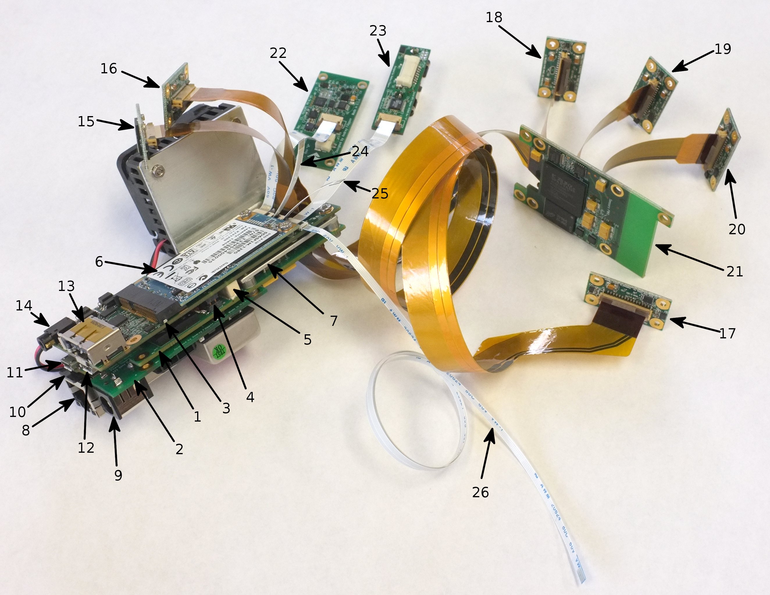
With all three of the new boards for the NC393 series cameras assembled (but only partially tested) it is now possible to connect them with the existent components and show some possible configurations. Main applications of Elphel cameras are scientific research, system prototyping, proofs of concepts designs – areas that routinely require unique configurations, and this new camera series will continue tradition of high modularity.
The camera boards look nothing like Lego blocks, but nevertheless they can zip together in different ways allowing to make new systems with minimal additional hardware. Elphel new design values our prior work (hardware development is still expensive) and provides compatibility with the existent modules, simultaneously enabling new features that were not previously possible, The most obvious example – sensor interface. The 10393 board is designed to accommodate our existent sensor front ends, custom flex cables of different lengths and shapes. That will help us to reduce the transition period to the new camera so we can focus on the high performance system board and port portions of the software and FPGA code, code that is already proven to work.
The same camera sensor ports will allow us to use multi-lane serial sensor connections needed for the modern high speed and high resolution devices, but we will work on this only after the first part will be done and we will be able to replace our current systems with the new ones. Implementation of the serial sensor connection has some challenges for us because the used protocols are not open and we have to rely only on the pieces of the available information and some reverse-engineering and research. It is not the most fun work to do, but being an Open Hardware/ Free Software company we will not provide our users with semi-open documentation. Our users will always be able to rebuild all the binaries from the source code – same binaries from the same code we have access ourselves. The only NDA Elphel ever signed was with Kodak – that sensor NDA had clear expiration time, so at the moment we planned to start distributing our products (and so the source documentation) we were not be bound by it anymore.
Sample configuration illustrated below combines the new and existent modules, the later have links to the design documentation on Elphel wiki. It is not so for the new boards (10393, 10385, 10389) – no circuit diagrams, parts lists or PCB layouts are publicly available when this post is being written. Hardware errors are usually much more expensive to fix, and we do not want somebody to duplicate our hardware “bugs” until we consider our products (“binaries”) to be good enough to go to our users. So while we set up public Git repository when we start software development, we publish our hardware documentation simultaneously with the start of the product distribution – together with “binaries”, not ahead of them.

Sample configuration of the electronic modules of Elphel NC393 camera family
November 2, 2013
by Andrey Filippov
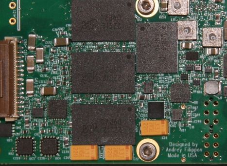
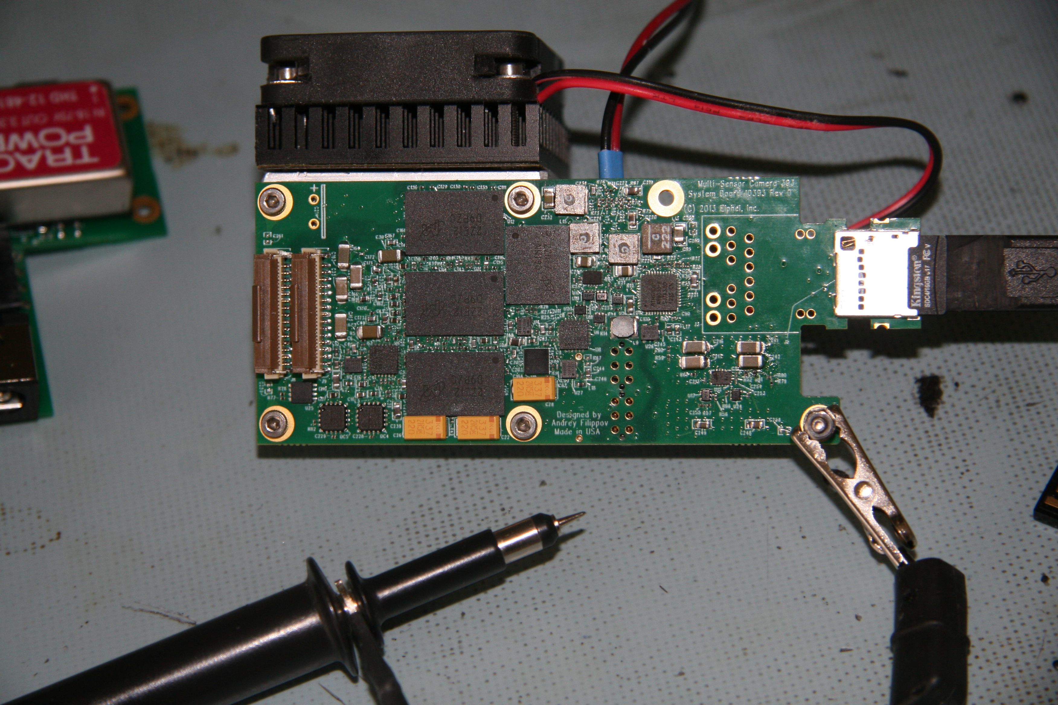
10393 board, memory side
We received the first prototype of the 10393 rev.’0″ – the new camera system board with all the BGA chips mounted. It took a little longer as our PCB assembly manufacturer had to order solder paste stencils as some chips (DC-DC converter module in LGA package and QFN chips with central thermal pads) required more than just applying tacky flux and running them through the reflow oven. The photo shows the 10393 system board together with the 10385 power supply board that I assembled earlier while waiting for the main one. This time the power supply is a separate module so we’ll not need different system board versions for different power supply options as we do with Elphel current NC353.
(more…)
October 2, 2013
by Andrey Filippov
In this post I write about our current development, my first experience with Xilinx Zynq, and also try to summarize the 10+ years experience with Xilinx FPGA devices. It is a mixture of the admiration for their state of the art silicon devices and frustration caused by the software. Please excuse my sometimes harsh words and analogies – I really would like to see Xilinx prosper and acquire software vision that matches the freedom that Ross Freeman brought to developers of the electronic devices when he invented FPGA and started Xilinx.
(more…)
July 27, 2013
by Andrey Filippov

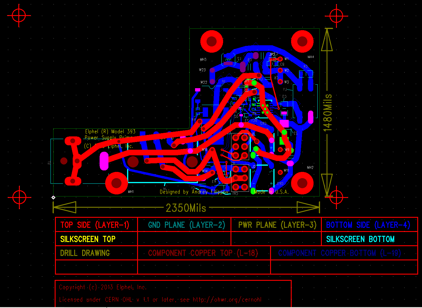
10385 – Power supply board layout
There is a small update to the previous post – circuit design and the PCB layout is done for the two companion boards. And it lead to some re-design on the system board. When working on the power supply board (it provides camera with the regulated 3.3V from the external source) I realized that it will have to hang on just two screws – not good for a rather heavy board with Traco DC/DC module (same size as the one currently used in
Elphel NC353L camera). The 10393 system board and the 10389 Interface/SSD boards will be mounted on two sides of the aluminum heat sink plate (CNC-ed to match component heights) and the smaller 10385 will sit on top of the 10393, and all the 10385 mount screws have to go through the system board. So I had to add additional holes near the middle of the 10393. That in turn required to move the 40-pin inter-board connector that carries SATA, USB, synchronization and additional general purpose signals to the 10389. So I had to re-route part of the design, but it was a right time to do as none of the boards was released yet leaving the freedom for such modifications. These new holes will also improve the mounting of the heat sink to the Zynq chip (the large white square on the 10393 layout below).
(more…)
July 13, 2013
by Andrey Filippov
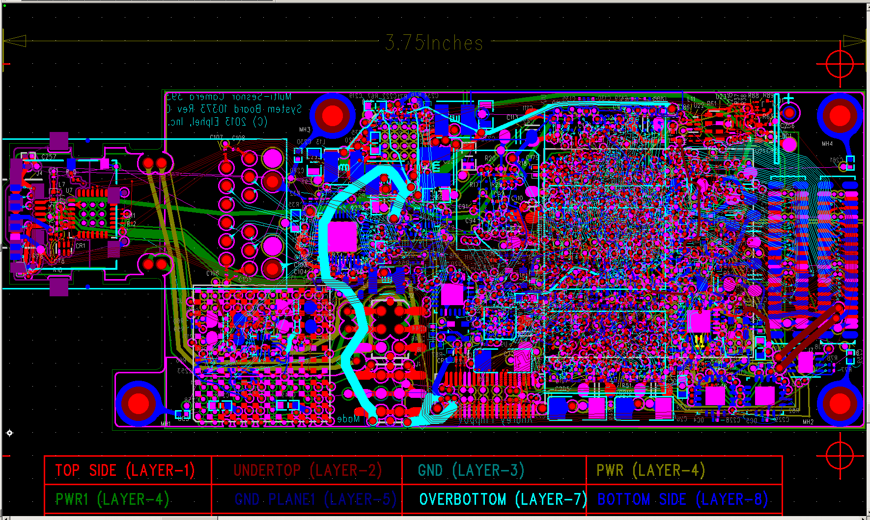
Development of the NC393 is now started, at last – last 6 weeks I’m working on it full time. It is still a long way ahead before the new camera will replace our current model 353, but at least the very first step is completed – I just finished the PCB layout of the system board.
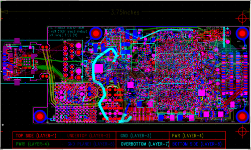
10393 System Board PCB layout
There were not so many changes to the specs/features that were planned and described in the October 2012 post, the camera will be powered by Xilinx Zynq SoC (XC7Z030-1FBG484C to be exact) that combines high performance FPGA with a dual ARM CPU and generous set of built-in peripherals. It will have 1GB of on-board system memory and 512MB of additional dedicated video/FPGA memory (the NC353 has 64MB each of them). Both types of memory consist of the same 256Mx16 DDR3 chips – 2 for the system (to use full available memory bus width of 32 bits) and one for the FPGA.
The main class of the camera applications remains to be a multi-sensor. Even more so – the smallest package of the Zynq 7030 device turned out to have sufficient number of I/Os to accommodate 4 sensor ports – originally I planned only 3 of them. These sensor ports are fully compatible with our current 5MPix sensor boards and with the existent 10359 sensor multiplexer boards – with such multiplexers it will be possible to control up to 12 sensors with a single 10393. Four of the connectors are placed in two pairs on both sides of the PCB, so they overlap on the layout image.
(more…)
« Previous Page —
Next Page »
