by Andrey Filippov
Fig.1. Image comparison of the different processing stages output
Results of the processing of the color image
Previous blog post “Lens aberration correction with the lapped MDCT” described our experiments with the lapped MDCT[1] for optical aberration corrections of a single color channel and separation of the asymmetrical kernel into a small asymmetrical part for direct convolution and a larger symmetrical one to be applied in the frequency domain of the MDCT. We supplemented this processing chain with additional steps of the image conditioning to evaluate the overall quality of the of the results and feasibility of the MDCT approach for processing in the camera FPGA.
Image comparator in Fig.1 allows to see the difference between the images generated from the results of the several stages of the processing. It makes possible to compare any two of the image layers by either sliding the image separator or by just clicking on the image – that alternates right/left images. Zoom is controlled by the scroll wheel (click on the zoom indicator fits image), pan – by dragging.
Original image was acquired with Elphel model 393 camera with 5 Mpix MT9P006 image sensor and Sunex DSL227 fisheye lens, saved in jp4 format as a raw Bayer data at 98% compression quality. Calibration was performed with the Java program using calibration pattern visible in the image itself. The program is designed to work with the low-distortion lenses so fisheye was a stretch and the calibration kernels near the edges are just replicated from the ones closer to the center, so aberration correction is only partial in those areas.
First two layers differ just by added annotations, they both show output of a simple bilinear demosaic processing, same as generated by the camera when running in JPEG mode. Next layers show different stages of the processing, details are provided later in this blog post.
(more…)
by Andrey Filippov
Modern small-pixel image sensors exceed resolution of the lenses, so it is the optics of the camera, not the raw sensor “megapixels” that define how sharp are the images, especially in the off-center areas. Multi-sensor camera systems that depend on the tiled images do not have any center areas, so overall system resolution may be as low as that of is its worst part.
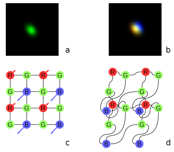
Fig. 1. Lateral chromatic aberration and Bayer mosaic: a) monochrome (green) PSF, b) composite color PSF, c) Bayer mosaic of the sensor, d) distorted mosaic for the chromatic aberration of b).
De-mosaic processing and chromatic aberrations
Our current cameras role is to preserve the raw sensor data while providing some moderate compression, all the image correction is applied during post-processing. Handling the lens aberration has to be done before color conversion (or de-mosaicing). When converting Bayer data to color images most cameras start with the calculation of the “missing” colors in the RG/GB pattern using 3×3 or 5×5 kernels, this procedure relies on the specific arrangement of the color filters.
Each of the red and blue pixels has 4 green ones at the same distance (pixel pitch) and 4 of the opposite (R for B and B for R) color at the equidistant diagonal locations. Fig.1. shows how lateral chromatic aberration disturbs these relations.
Fig.1a is the point-spread function (PSF) of the green channel of the sensor. The resolution of the PSF measurement is twice higher than the pixel pitch, so the lens is not that bad – horizontal distance between the 2 greens in Fig.1c corresponds to 4 pixels of Fig.1a. It is also clearly visible that the PSF is elongated and the radial resolution in this part of the image is better than the tangential one (lens center is left-down).
Fig.1b shows superposition of the 3 color channels: blue center is shifted up-and-right by approximately 2 PSF pixels (so one actual pixel period of the sensor) and the red one – half-pixel left-and-down from the green center. So the point light of a star, centered around some green pixel will not just spread uniformly to the two “R”s and two “B”s shown connected with lines in Fig.1c, but the other ones and in different order. Fig.1d illustrates the effective positions of the sensor pixels that match the lens aberration.
(more…)