by Mikhail Karpenko
Sometimes we need to test disks connected to camera and find out if a particular model is a good candidate for in-camera stream recording application. Such disks should not only be fast enough in terms of write speed, but they should have short ‘response time’ to write commands. This ‘response time’ is basically the time between command sent to disk and a response from disk that this command has finished. The time between the two events is related to total write speed, but it can vary due to processes going on in internal disk controller. The fluctuations in disk response time can be an important parameter for high bandwidth streaming applications in embedded systems as this value allows to estimate the data buffer size needed during recording, but this may be not very critical parameter for typical PC applications as modern computers are equipped with large amount of RAM. We have not found any suitable parameter in disk specifications we had which would give us a hint for the buffer size estimation and developed a small test program for this purpose.
(more…)
by Andrey Filippov
As we finished with the basic camera functionality and tested the first Eyesis4π built with the new 10393 system boards (it is smaller, requires less power and, is faster) we are moving forward with the in-camera image processing. We plan to combine our current camera calibration methods that require off-line post processing and the real-time image correction using the camera own FPGA resources. This project development will require switching between the actual FPGA coding and the software implementation of the same algorithms before going to the next step – software is still easier to design. The first part was in FPGA realm – it was to implement the fundamental image processing block that we already know we’ll be using and see how much of the resources it needs.
DCT type IV as a building block for in-camera image processing
We consider a small (8×8 pixel) DCT-IV to be a universal block for conditioning of the raw acquired images. Such operations as lens optical aberrations correction, color conversion (de-mosaic) in the presence of the lateral chromatic aberration, image rectification (de-warping) are easier to perform in the frequency domain using convolution-multiplication property and other algorithms.
In post-processing we use DFT (Discrete Fourier Transform) over rather large (64×64 to 512×512) tiles, but that would be too much for the in-camera processing. First is the tile size – for good lenses we do not need that large convolution kernels. Additionally we plan to combine several processing steps into one (based on our off-line post-processing experience) and so we do not need to sub-sample images – in our current software we double resolution of the raw images at the beginning and scale back the final result to reduce image degradation caused by re-sampling.
The second area where we plan to reduce computations is the replacement of the DFT with the DCT that is designed to be fed with the pure real data and so requires less arithmetic operations than DFT that processes complex input values.
Why “type IV” of the DCT?
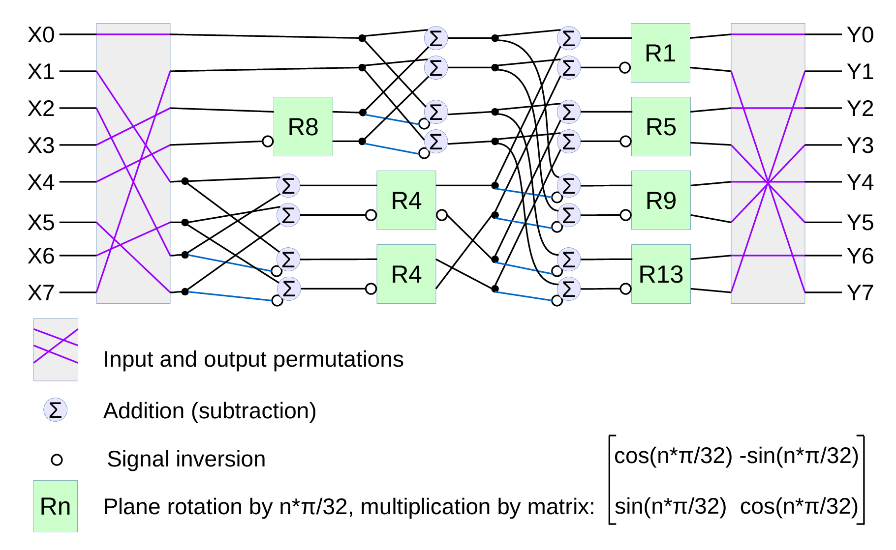
Fig.1. Signal flow graph for DCT-IV
We already have DCT type II implemented for the JPEG/JP4 compression, and we still needed another one. Type IV is used in audio compression because it can be converted to a modified discrete cosine transform (MDCT) – a procedure when multiple overlapped windows are processed one at a time and the results are seamlessly combined without any block artifacts that are familiar for the JPEG with low settings of the compression quality. We too need lapped transform to process large images with relatively small (much smaller than the image itself) convolution kernels, and DCT-IV is a perfect fit. 8-point DCT-IV allows to implement transformation of 16-point segments with 8-point overlap in a reversible manner – the inverse transformation of 8-point data may be converted to 16-point overlapping segments, and being added together these segments result in the original data.
(more…)