by Andrey Filippov
Elphel cameras offer unique capabilities – they are high performance systems out of the box and have all the firmware and FPGA code distributed under GNU General Public Licenses making it possible for users to modify any part of the code. The project does not use any “black boxes” or encrypted modules, so it is simulated with the free software tools and user has access to every net in the design. We are trying to do our best to make this ‘hackability’ not just a theoretical possibility, but a practical one.
Current camera FPGA project contains over 400 files under version control and almost 100K lines of HDL (Verilog) code, there are also constraints files, tool configurations, so we need to provide means for convenient navigation and modification of the project by the users.
We are starting a series of tutorials to facilitate acquaintance with this project, and here is the first one that shows how to install and configure the software. This tutorial is made with a fresh Kubuntu 16.04 LTS distribution installed on a virtual machine – this flavor of GNU/Linux we use ourselves and so it is easier for us to help others in the case of problems, but it should be also easy to install it on other GNU/Linux systems.
Later we plan to show how to navigate code and view/modify tool parameters with VDT plugin, run simulation and implementation tools. Next will be a “Hello world” module added to the camera code base, then some simple module that accesses the video memory.
Video resolution is 1600×900 pixels, so full screen view is recommended.
Download links for: video and captions.
Running this software does not require to have an actual camera, so it may help our potential users to evaluate software capabilities and see if it matches their requirements before purchasing an actual hardware. We will also be able to provide remote access to the cameras in our office for experimenting with them.
by Andrey Filippov
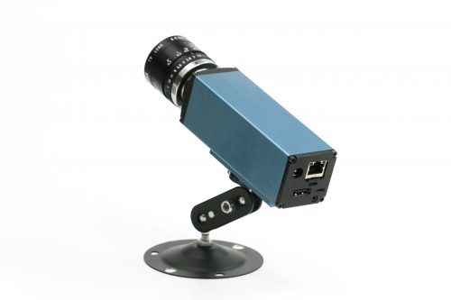
Two weeks ago we were making photos of our first production NC393 camera to post an announcement of the new product availability. We got all the mechanical parts and most of the electronic boards (14MPix version will be available shortly) and put them together. Nice looking camera, powered by a high performance SoC (dual ARM plus FPGA), packaged in a lightweight aluminum extrusion body, providing different options for various environments – indoors, outdoors, on board of the UAV or even in the open space with no air (cooling is important when you run most of the FPGA resources at full speed). Tons of potential possibilities, but the finished camera did not seem too exciting – there are so many similar looking devices available.
-
-
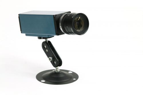
NC393 camera, front view
-
-
NC393 camera, back view
-

-
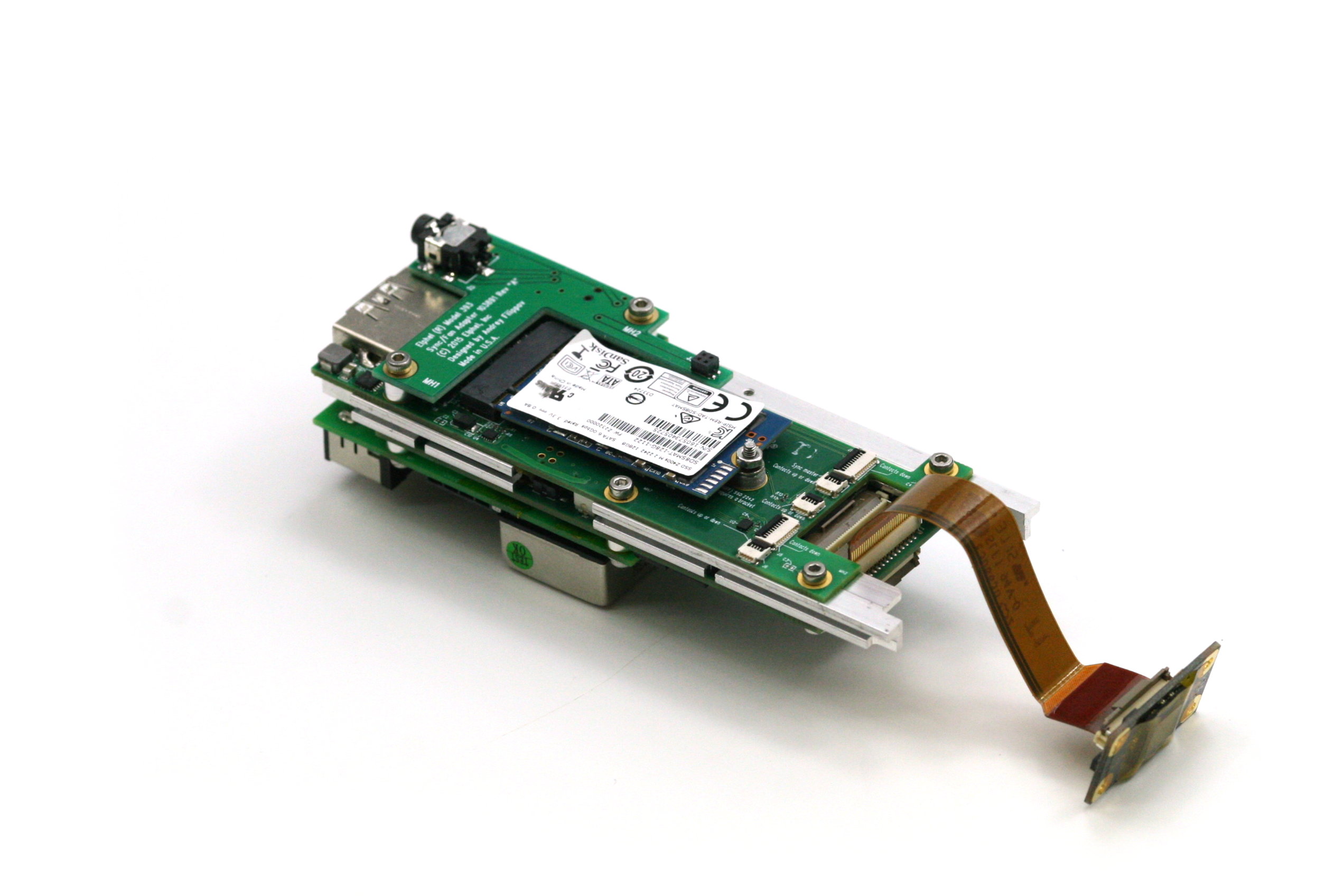
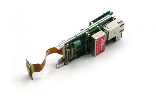
NC393 assembled boards: 10393(system board), 10385 (power supply board), 10389(interface board), 10338e (sensor board) and 103891 – synchronization adapter board, view from 10389
-
-
NC393 assembled boards: 10393(system board), 10385 (power supply board), 10389(interface board), 10338e (sensor board) and 103891 – synchronization adapter board, view from 10385
-

-
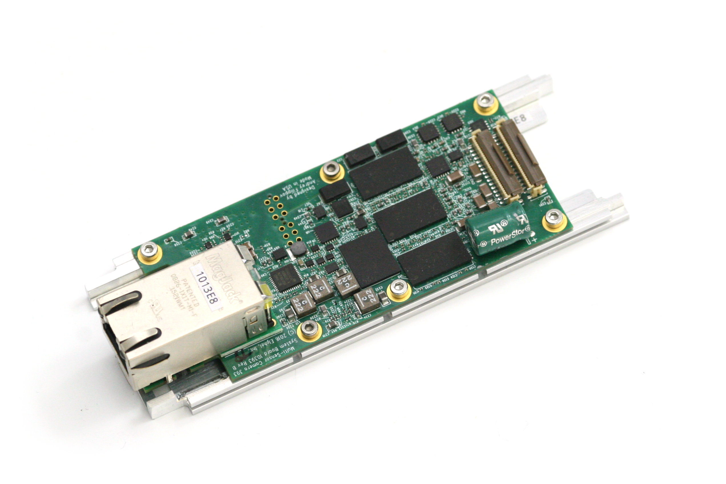
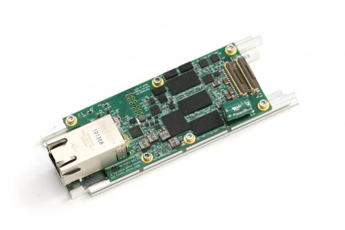
10393 system board attached to the heat frame, view from the heat frame
-
-
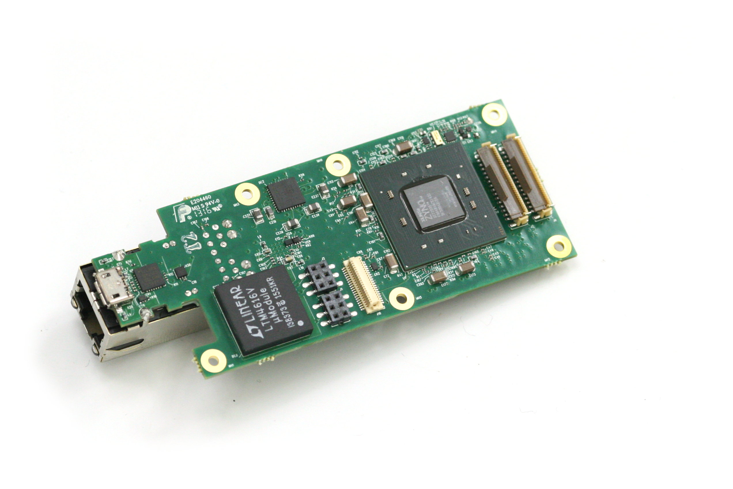
10393 system board attached to the heat frame, view from the 10393 board
-
-
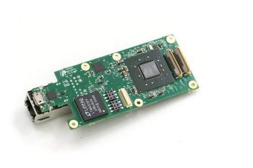
10393 system board, view from the processor side
An obvious reason for our dissatisfaction is that the single-sensor camera uses just one of four available sensor ports. Of course it is possible to use more of the freed FPGA resources for a single image processing, but it is not what you can use out of the box. Many of our users buy camera components and arrange them in their custom setup themselves – that does not have a single-sensor limitation and it matches our goals – make it easy to develop a custom system, or sculpture the camera to meet your ideas as stated on our web site. We would like to open the cameras to those who do not have capabilities of advanced mechanical design and manufacturing or just want to try new camera ideas immediately after receiving the product.
(more…)