Photogrammetric Calibration of the Quad Thermal Camera
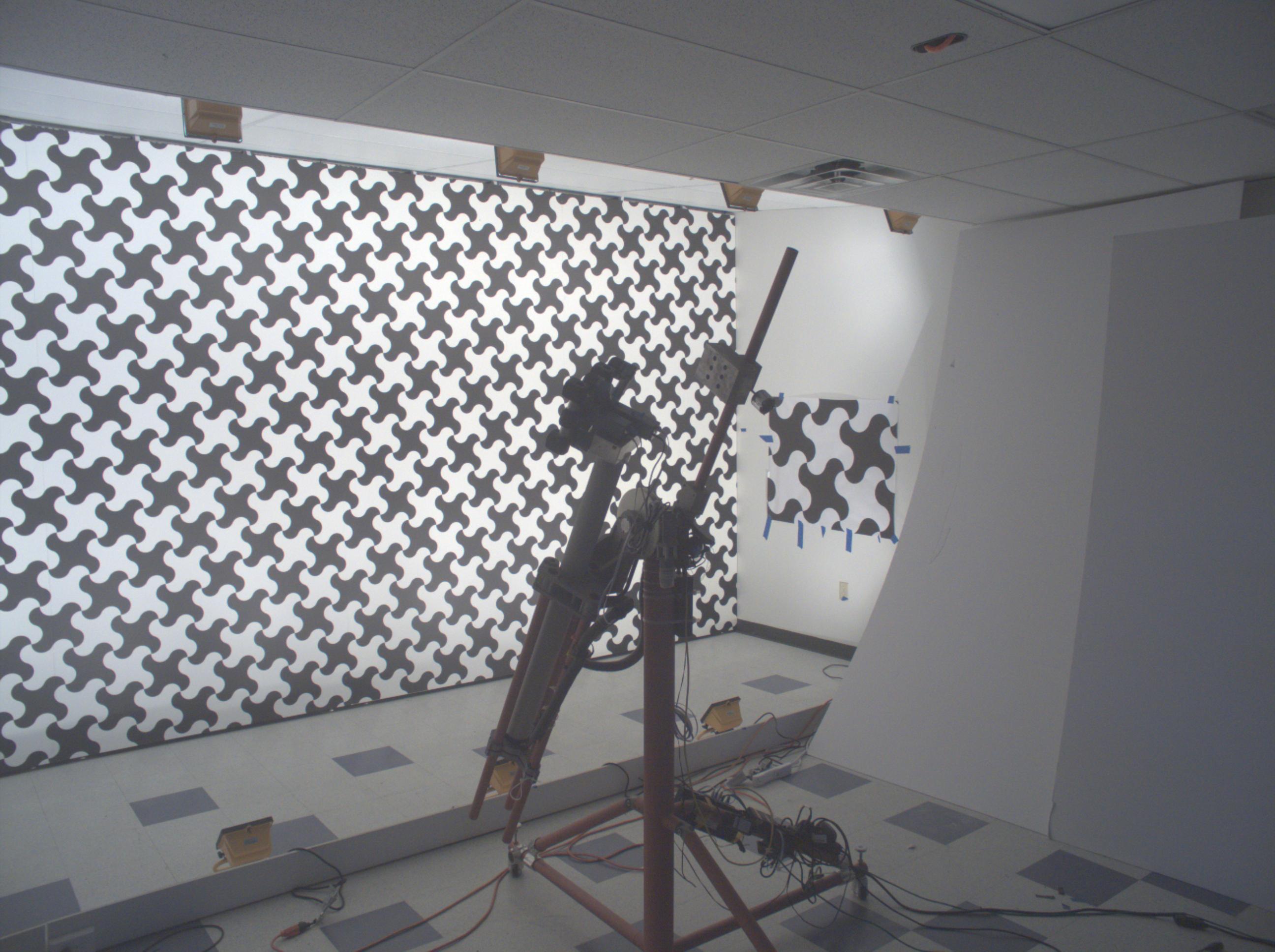
Figure 1. Calibration of the quad visible range + quad LWIR camera.
We’ve got the first results of the photogrammetric calibration of the composite (visible+LWIR) Talon camera described int the previous post and tested the new pattern. In the first experiments with the new software code we’ve got average reprojection error for LWIR of 0.067 pix, while the visible quad camera subsystem was calibrated down to 0.036 pix. In the process of calibration we acquired 3 sequences of 8-frame (4 visible + 4 LWIR) image sets, 60 sets from each of the 3 camera positions: 7.4m from the target on the target center line, and 2 side views from 4.5m from the target and 2.2 m right and left from the center line. From each position camera axis was scanned in the range of ±40° horizontally and ±25° vertically.
In the first stage of calibration the acquired images (Figure 2 shows both LWIR and visible range images) were processed to extract the detected pattern grid node. Each node’s pixel coordinates (x,y), a pair of the pattern UV indexes and the contrast are stored in the form of multi-layer TIFF files – processed images from Figure 2 are shown on animated GIFs, Figure 3 is for LWIR and Figure 4 – for the visible range images. Each of the images has a link to a respective TIFF file that has metadata visible with ImageJ program.
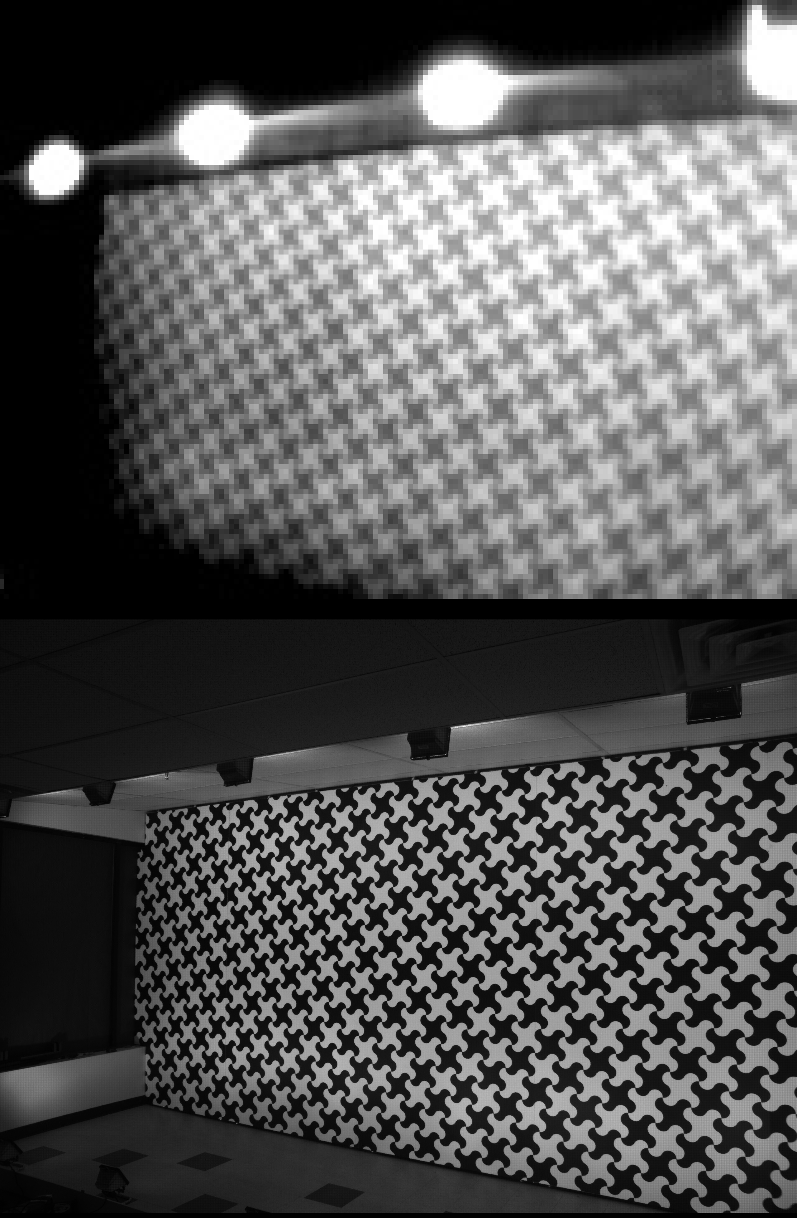
Figure 2. LWIR and visible range images of the pattern.
The software for the calibration had to be modified, as it did not have provisions for handling different resolution sensors in the same system. Additionally it was designed for the smaller pattern cell size so each image had larger number of detected nodes. We also had to use other method of absolute pattern matching (finding out which of the multiple almost identical measure nodes corresponds to the particular (e.g. center) node of the physical pattern. Earlier, with the fine pitch patterns, we used software-controlled laser pointers, with the current approach we used the fact that the visible subsystem was already calibrated – that provided sufficient data for absolute matching. Only one image for each camera position had manually marked center pattern cell – that mark simplified the processing.
Before LWIR data was used the visible rage images were processed with Levenberg-Marquardt algorithm (LMA) and the system knew precise position and orientation of the camera during capturing of each image set. After preliminary adjustment with idealized (uniform and flat) pattern grid it was possible to simultaneously refine each physical pattern node location in 3d, similarly as we did earlier (Figures 4 and 5 in this post). Using large cell pattern, the visible cameras bundle adjustment resulted in 0.11 pixels when using just radial distortion model. This was improved to 0.036 pix when using non-radial correction to compensate other irregularities of the lenses.
When LWIR data was added and each image set had known extrinsic parameters, the absolute grid matching was performed in the following way. Starting with the image with the smallest distance from the target (so the wrong matching of the grid cell would cause attitude error larger than initial precision of the system assembly) the attitude angles of each of the 4 LWIR subcameras was found. Then for each additional image LMA was run with all but 2 parameters known and fixed – camera base position X and Y coordinates (in the plane parallel to the target). As the position was already known from the visible range subsystem, the X and Y difference was matched to the physical pattern dimensions to determine how many cells (if any) the assumed grid match is offset. That gave absolute grid match for all of the LWIR images, and bundle adjustment of the LWIR modules intrinsic (focal length, offset from the center pixel, radial distortion coefficient) as well as the modules location in the camera coordinate system and their attitudes was possible. It resulted in 0.097 pixels reprojection error with just the radial distortion model. We did not expect much from the non-radial correction as the sensor resolution is low, but it still gave some improvement – the residual error dropped down to 0.067 pix. It is likely this value can be improved more with better tweaking of the processing parameters – the current result was achieved in the first run.
 Figure 3. Processed pattern grid from LWIR data (click image to download ImageJ Tiff stack). |
 Figure 4. Processed pattern grid from visible range camera data (click image to download ImageJ Tiff stack). |
These calibration results are not that exciting compared to what we will get with the LWIR 3D model reconstruction, but it gives us confidence that we are on the right track, and our goal is possible. Having a much higher resolution sub-system conveniently provides ground truth data for training of the neural network – something that was much more difficult to achieve with the high resolution visible range only systems.
hi!
I have a question in the blog post.
I wonder if you used a pattern of that special pattern instead of a regular square grid pattern.
We used a modified checkerboard pattern (each edge replaced by a pair of arcs), the same design as we used for the visible range camera calibration. Such design has a richer spatial spectrum (squares have all frequency-domain energy concentrated in two lines); this is used for point-spread function (PSF) measurement for aberration correction.
Andrey
Happy New Year 2021
Thanks for replying. I have a question, so I ask.
1. Is there a paper you referenced about why it is good to use this pattern?
We would be grateful if you let us know specifically why this pattern is good.
2. You said that the square pattern has all the frequency domain energy concentrated in two lines. It would be appreciated if you could inform us in more detail. I’m not sure what exactly the two lines you said mean.
Thank you
Here is the comparison of the patterns:
https://blog.elphel.com/2010/11/zoom-in-now-enhance/#Selecting_test_pattern_for_the_PSF_measurement
Andrey