August 4, 2019
by Andrey Filippov
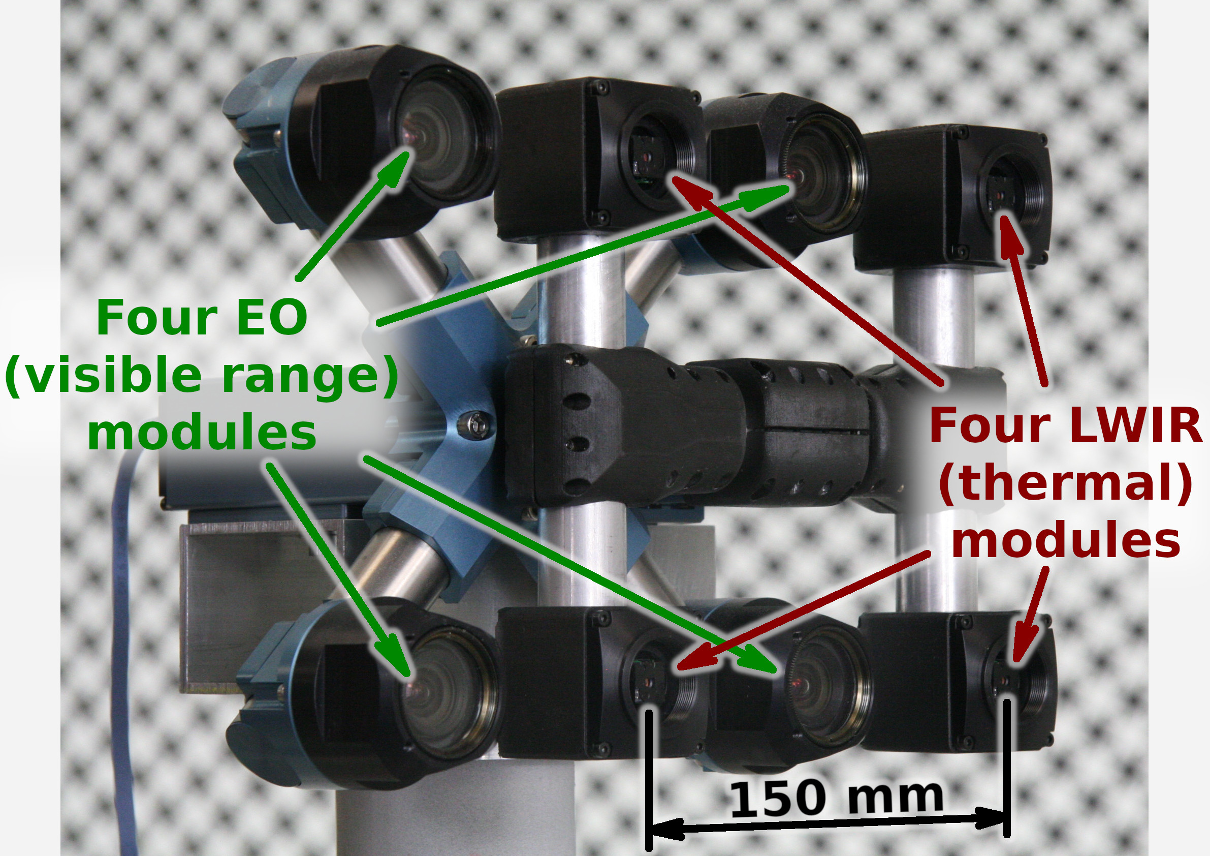
Figure 1. Talon (“instructor/student”) test camera.
Update: arXiv:1911.06975 paper about this project.
Summary
This post concludes the series of 3 publications dedicated to the progress of Elphel five-month project funded by a SBIR contract.
After developing and building the prototype camera shown in Figure 1, constructing the pattern for photogrammetric calibration of the thermal cameras (post1), updating the calibration software and calibrating the camera (post2) we recorded camera image sets and processed them offline to evaluate the result depth maps.
The four of the 5MPix visible range camera modules have over 14 times higher resolution than the Long Wavelength Infrared (LWIR) modules and we used the high resolution depth map as a ground truth for the LWIR modules.
Without machine learning (ML) we received average disparity error of 0.15 pix, trained Deep Neural Network (DNN) reduced the error to 0.077 pix (in both cases errors were calculated after removing 10% outliers, primarily caused by ambiguity on the borders between the foreground and background objects), Table 1 lists this data and provides links to the individual scene results.
For the 160×120 LWIR sensor resolution, 56° horizontal field of view (HFOV) and 150 mm baseline, disparity of one pixel corresponds to 21.4 meters. That means that at 27.8 meters this prototype camera distance error is 10%, proportionally lower for closer ranges. Use of the higher resolution sensors will scale these results – 640×480 and longer baseline of 200 mm (instead of the current 150 mm) will yield 10% accuracy at 150 meters, 56°HFOV.
(more…)
June 18, 2019
by Andrey Filippov
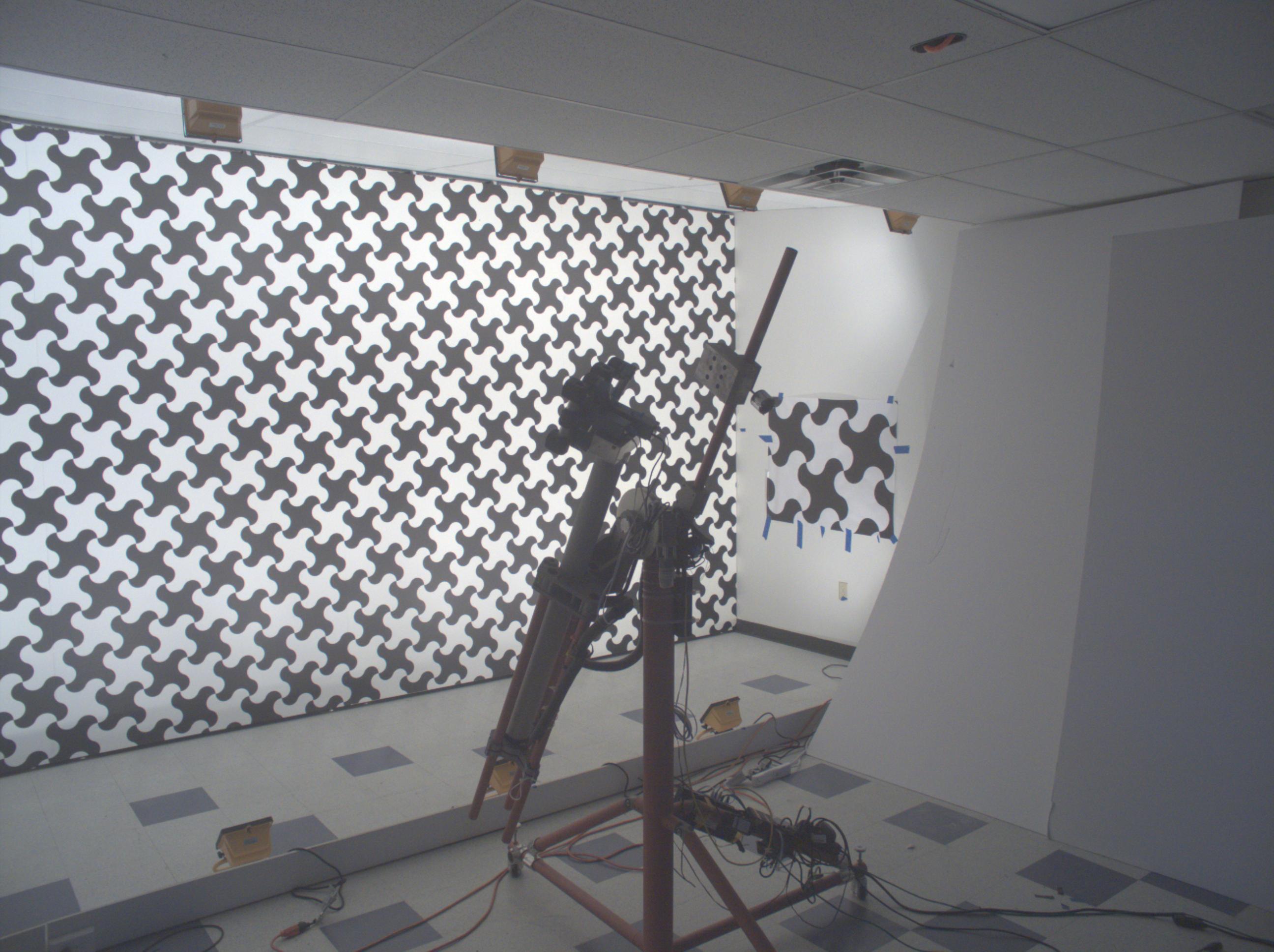
Figure 1. Calibration of the quad visible range + quad LWIR camera.
We’ve got the first results of the photogrammetric calibration of the composite (visible+LWIR) Talon camera described int the previous post and tested the new pattern. In the first experiments with the new software code we’ve got average reprojection error for LWIR of 0.067 pix, while the visible quad camera subsystem was calibrated down to 0.036 pix. In the process of calibration we acquired 3 sequences of 8-frame (4 visible + 4 LWIR) image sets, 60 sets from each of the 3 camera positions: 7.4m from the target on the target center line, and 2 side views from 4.5m from the target and 2.2 m right and left from the center line. From each position camera axis was scanned in the range of ±40° horizontally and ±25° vertically.
(more…)
June 6, 2019
by Andrey Filippov
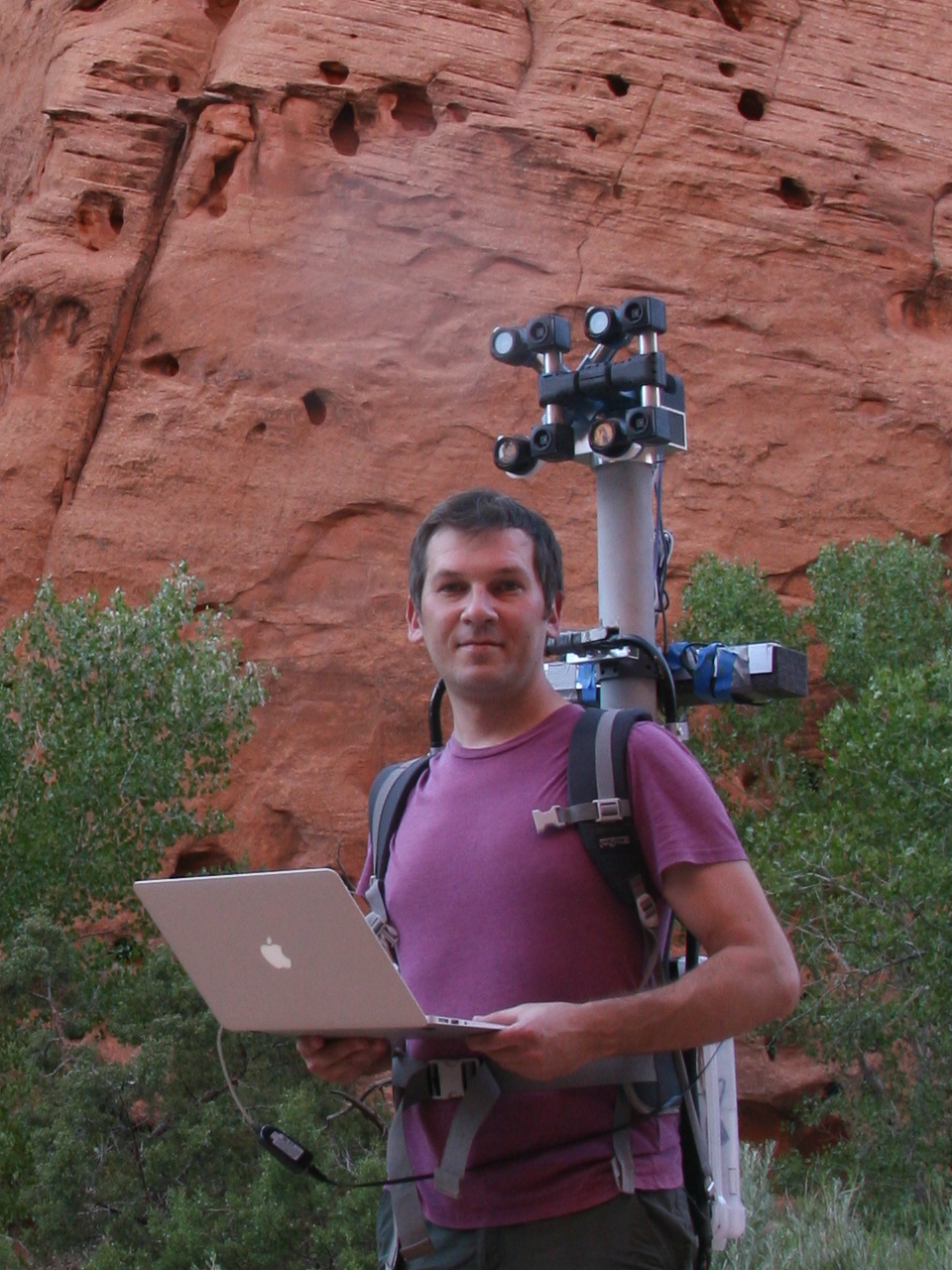
Figure 1. Oleg carrying combined LWIR and visible range camera.
While working on extremely long range 3D visible range cameras we realized that the passive nature of such 3D reconstruction that does not involve flashing lasers or LEDs like LIDARs and Time-of-Flight (ToF) cameras can be especially useful for thermal (a.k.a LWIR – long wave infrared) vision applications. SBIR contract granted at the AF Pitch Day provided initial funding for our research in this area and made it possible.
We are now in the middle of the project and there is a lot of the development ahead, but we have already tested all the hardware and modified our earlier code to capture and detect calibration pattern in the acquired images.
(more…)
September 20, 2017
by Andrey Filippov
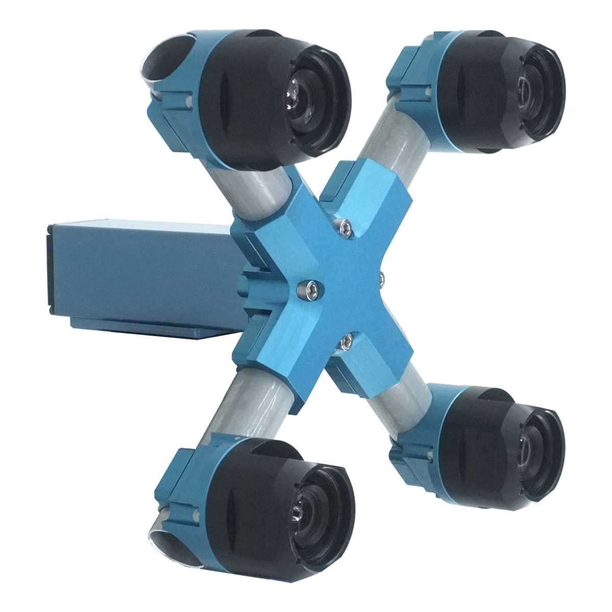
Figure 1. Four sensor stereo camera
January 19, 2017
by Andrey Filippov
Fig.1. Image comparison of the different processing stages output
Results of the processing of the color image
Previous blog post
“Lens aberration correction with the lapped MDCT” described our experiments with the lapped MDCT
[1] for optical aberration corrections of a single color channel and separation of the asymmetrical kernel into a small asymmetrical part for direct convolution and a larger symmetrical one to be applied in the frequency domain of the MDCT. We supplemented this processing chain with additional steps of the image conditioning to evaluate the overall quality of the of the results and feasibility of the MDCT approach for processing in the camera FPGA.
Image comparator in Fig.1 allows to see the difference between the images generated from the results of the several stages of the processing. It makes possible to compare any two of the image layers by either sliding the image separator or by just clicking on the image – that alternates right/left images. Zoom is controlled by the scroll wheel (click on the zoom indicator fits image), pan – by dragging.
Original image was acquired with Elphel model 393 camera with 5 Mpix MT9P006 image sensor and Sunex DSL227 fisheye lens, saved in
jp4 format as a raw Bayer data at 98% compression quality. Calibration was performed with the Java
program using calibration pattern visible in the image itself. The program is designed to work with the low-distortion lenses so fisheye was a stretch and the calibration kernels near the edges are just replicated from the ones closer to the center, so aberration correction is only partial in those areas.
First two layers differ just by added annotations, they both show output of a simple bilinear demosaic processing, same as generated by the camera when running in JPEG mode. Next layers show different stages of the processing, details are provided later in this blog post.
(more…)
January 7, 2017
by Andrey Filippov
Modern small-pixel image sensors exceed resolution of the lenses, so it is the optics of the camera, not the raw sensor “megapixels” that define how sharp are the images, especially in the off-center areas. Multi-sensor camera systems that depend on the tiled images do not have any center areas, so overall system resolution may be as low as that of is its worst part.
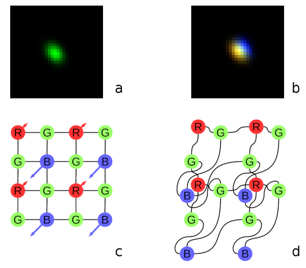
Fig. 1. Lateral chromatic aberration and Bayer mosaic: a) monochrome (green) PSF, b) composite color PSF, c) Bayer mosaic of the sensor, d) distorted mosaic for the chromatic aberration of b).
De-mosaic processing and chromatic aberrations
Our current cameras role is to preserve the raw sensor data while providing some moderate compression, all the image correction is applied during post-processing. Handling the lens aberration has to be done before color conversion (or de-mosaicing). When converting Bayer data to color images most cameras start with the calculation of the “missing” colors in the RG/GB pattern using 3×3 or 5×5 kernels, this procedure relies on the specific arrangement of the color filters.
Each of the red and blue pixels has 4 green ones at the same distance (pixel pitch) and 4 of the opposite (R for B and B for R) color at the equidistant diagonal locations. Fig.1. shows how lateral chromatic aberration disturbs these relations.
Fig.1a is the point-spread function (PSF) of the green channel of the sensor. The resolution of the PSF measurement is twice higher than the pixel pitch, so the lens is not that bad – horizontal distance between the 2 greens in Fig.1c corresponds to 4 pixels of Fig.1a. It is also clearly visible that the PSF is elongated and the radial resolution in this part of the image is better than the tangential one (lens center is left-down).
Fig.1b shows superposition of the 3 color channels: blue center is shifted up-and-right by approximately 2 PSF pixels (so one actual pixel period of the sensor) and the red one – half-pixel left-and-down from the green center. So the point light of a star, centered around some green pixel will not just spread uniformly to the two “R”s and two “B”s shown connected with lines in Fig.1c, but the other ones and in different order. Fig.1d illustrates the effective positions of the sensor pixels that match the lens aberration.
(more…)
September 10, 2014
by Andrey Filippov
We just tested two samples of Evetar N123B05425W lens that is very similar to
Sunex DSL945D described in the previous post.
Lens Specifications
|
Sunex DSL945D |
Evetar N123B05425W |
|---|
| Focal length |
5.5mm |
5.4mm |
| F# |
1/2.5 |
1/2.5 |
| IR cutoff filter |
yes |
yes |
| Lens mount |
M12 |
M12 |
| image format |
1/2.3 |
1/2.3 |
| Recommended sensor resolution |
10Mpix |
10MPix |
July 26, 2014
by Andrey Filippov
We were measuring lens performance since we’ve got involved in the optical issues of the camera design. There are several blog posts about it starting with "Elphel Eyesis camera optics and lens focus adjustment". Since then we improved methods of measuring Point Spread Function (PSF) of the lenses over the full field of view using the target pattern modified from the standard checkerboard type have better spatial frequency coverage. Now we use a large (3m x 7m) pattern for the lens testing, sensor front end (SFE) alignment, camera distortion calibration and aberration measurement/correction for Eyesis series cameras.
Fig.1 PSF measured over the sensor FOV – composite image of the individual 32×32 pixel kernels
So far lens testing was performed for just two purposes – select the best quality lenses (we use approximately half of the lenses we receive) and to precisely adjust the sensor position and tilt to achieve the best resolution over the full field of view. It was sufficient for our purposes, but as we are now involved in the custom lens design it became more important to process the raw PSF data and convert it to lens parameters that we can compare against the simulated achieved during the lens design process. Such technology will also help us to fine-tune the new lens design requirements and optimization goals.
The starting point was the set of the PSF arrays calculated using images acquired from the the pattern while scanning over the range of distances from the lens to the sensor in small increments as illustrated on the animated GIF image Fig.1. The sensor surface was not aligned to be perpendicular to the optical axis of the lens before the measurement -each lens and even sensor chip has slight variations of the tilt and it is dealt with during processing of the data (and during the final alignment of the sensor during production, of course). The PSF measurement based on the repetitive pattern gives sub-pixel resolution (1.1μm in our case with 2.2μm Bayer mosaic pixel period – 4:1 up-sampled for red and blue in each direction), but there is a limit on the PSF width that the particular setup can handle. Too far out-of-focus and the pattern can not be reliably detected. That causes some artifacts on the animations made of the raw data, these PSF samples are filtered during further processing. In the end we are interested in lens performance when it is almost in perfect focus, so scanning too far away does not provide much of the practical value anyway.
(more…)
June 30, 2014
by Oleg Dzhimiev
Elphel has embarked on a new project, somewhat different from our main field of designing digital cameras, but closely related to the camera applications and aimed to further improve image quality of Eyesis4π camera.
Eyesis4π is a high resolution full-sphere panoramic and stereophotogrammetric camera. It is a tiled multi-sensor system with a single sensor’s format of 1/2.5″. The specific requirement of such system is uniform angular resolution, since there is no center in a panoramic image.
(more…)
June 5, 2013
by Andrey Filippov

Fig.1. Elphel new calibration pattern
Elphel has moved to a new calibration facility in May 2013. The new office is designed with the calibration room being it’s most important space, expandable when needed to the size of the whole office with the use of wide garage door. Back wall in the new calibration room is covered with the large, 7m x 3m pattern, illuminated with bright fluorescent lights. The length of the room allows to position the calibration machine 7.5 meters away from the pattern. The long space and large pattern will allow to calibrate Eyesis4π positioned far enough from the pattern to be withing depth of field of its lenses focused for infinity, while still keeping wide angular size, preferred for accuracy of measurements.
We already hit the precision limits using the previous, smaller pattern 2.7m x 3.0m. While the software was designed to accommodate for the pattern where each of the nodes had to have individually corrected position (from the flat uniform grid), the process assumed that the 3d coordinates of the nodes do not change between measurements.
(more…)
Next Page »