NC393 development progress – 2
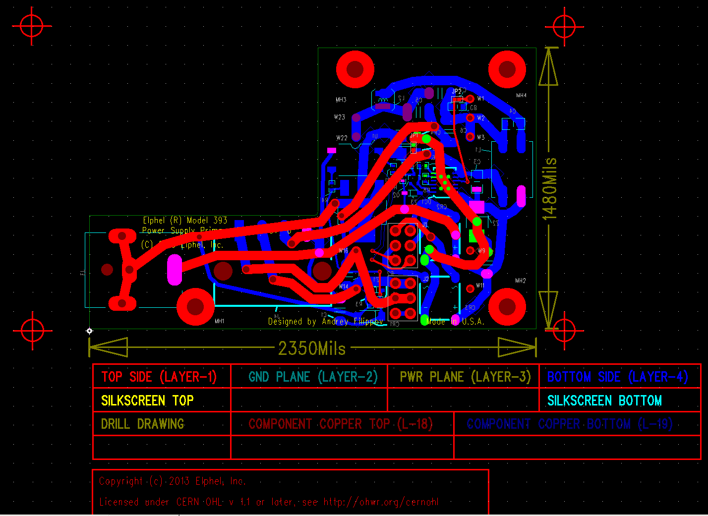
10385 – Power supply board layout
There is a small update to the previous post – circuit design and the PCB layout is done for the two companion boards. And it lead to some re-design on the system board. When working on the power supply board (it provides camera with the regulated 3.3V from the external source) I realized that it will have to hang on just two screws – not good for a rather heavy board with Traco DC/DC module (same size as the one currently used in Elphel NC353L camera). The 10393 system board and the 10389 Interface/SSD boards will be mounted on two sides of the aluminum heat sink plate (CNC-ed to match component heights) and the smaller 10385 will sit on top of the 10393, and all the 10385 mount screws have to go through the system board. So I had to add additional holes near the middle of the 10393. That in turn required to move the 40-pin inter-board connector that carries SATA, USB, synchronization and additional general purpose signals to the 10389. So I had to re-route part of the design, but it was a right time to do as none of the boards was released yet leaving the freedom for such modifications. These new holes will also improve the mounting of the heat sink to the Zynq chip (the large white square on the 10393 layout below).
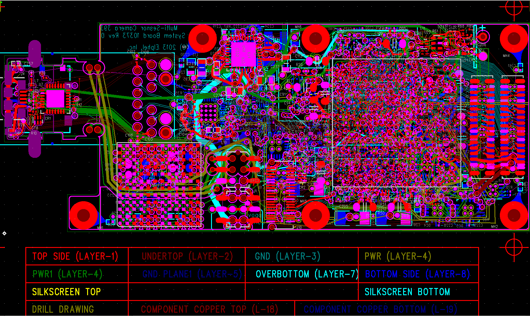
10393 – updated system board layout
Now when the core PCBs are designed (later will come new sensor boards and the successor to the current 10359 based on Xilinx XC7K160T to allow a single system board run up to 16 individual sensors), there is a boring part to double check all the pinouts and footprints of the new components, try to weed out as many other design errors as possible. Some will probably remain and will require re-spin of the boards, same as it was with our current camera. The 10353 system board is now revision “E” (6-th version), sensor board is also “E”, 10359 is “B” and the 10369 is “A”. But it will be very nice if the first prototype will be operational from the first attempt and the remaining bugs will not “brick” it completely, and we will be able to get enough information for implementing the needed changes. It did work this way before so I hope it will happen again. But still that boring part is ahead.
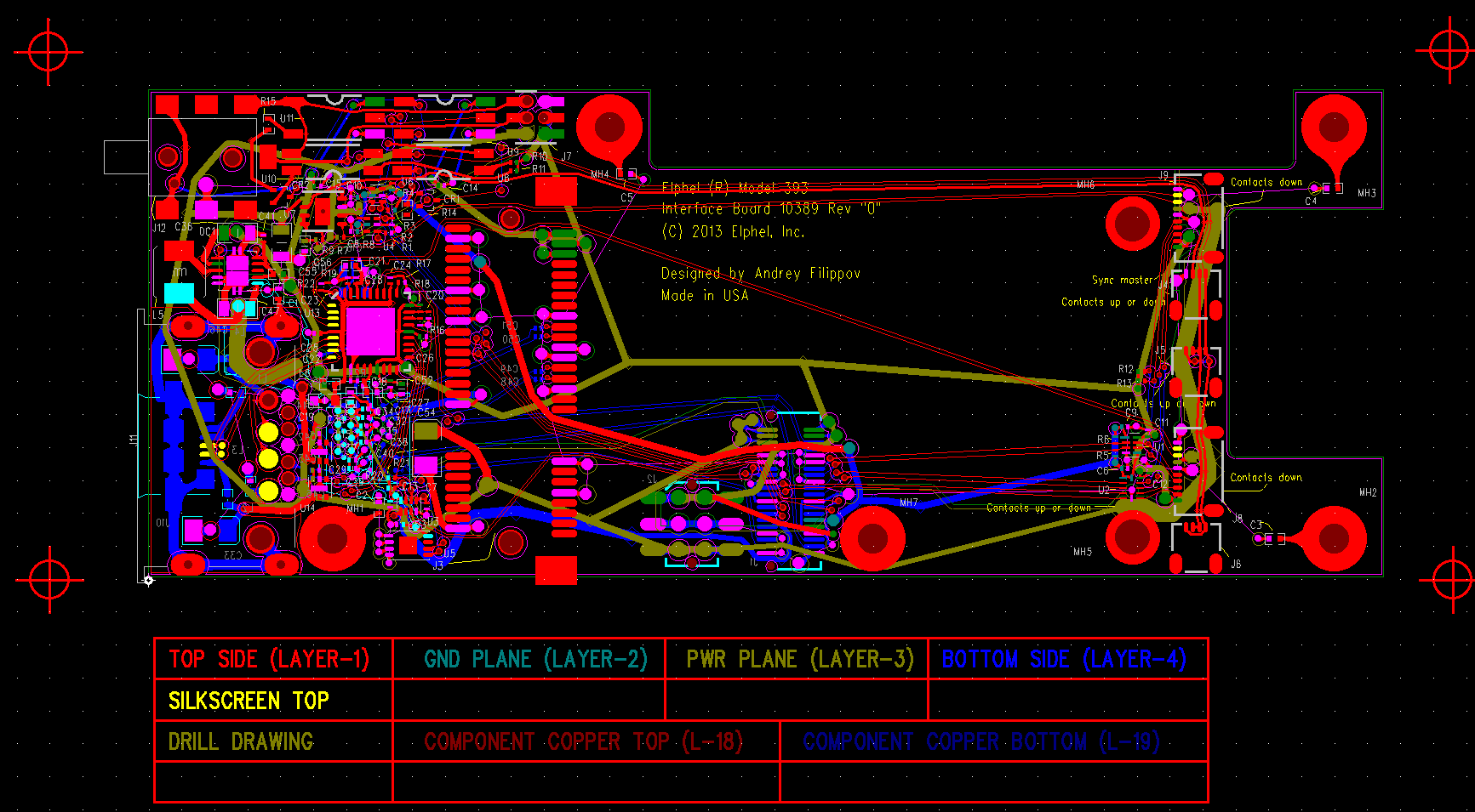
10389 – Interface/SSD board layout. Large part of the board is empty – this is the place for the SSD board
Leave a Reply