by Oleg Dzhimiev
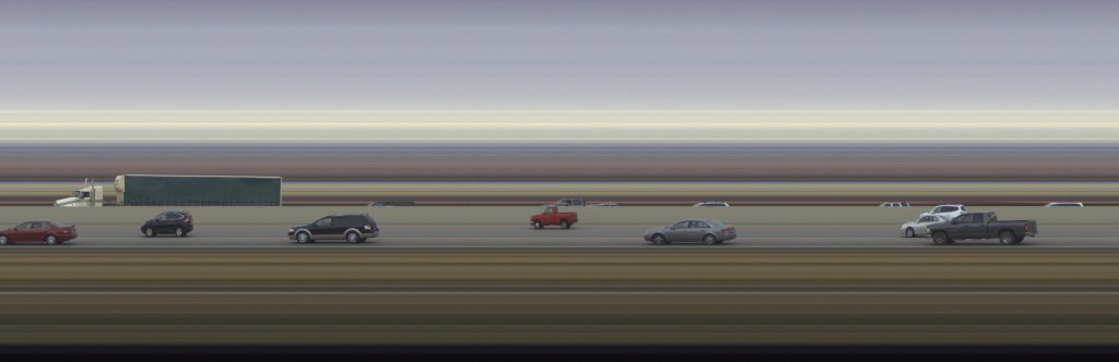
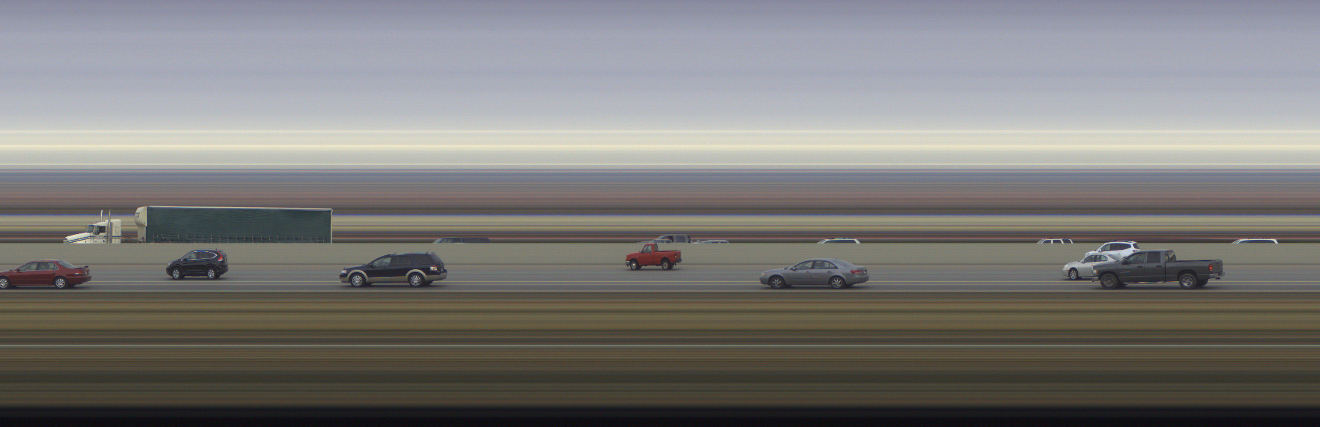
Photo Finish: all cars driving in the same direction effect
Since 2005 and the older 333 model, Elphel cameras have a Photo Finish mode. First, it was ported to 353 generation, and then from 353 to 393 camera systems.
In this mode the camera samples scan lines and delivers composite images as video frames. Due to the Bayer pattern of the sensor the minimal sample height is 2 lines. The max fps for the minimal sample height is 2300 line pairs per second. The max width of a composite frame can be up to 16384px (is determined by WOI_HEIGHT). A sequence of these frames can be simply joined together without any missing scan lines.
Current firmware (20180130) includes a photo finish demo: http://<camera_ip>/photofinish
A couple notes for 393 photo finish implementation:
- works in JP4 format (COLOR=5). Because in this format demosaicing is not done it does not require extra scan lines, which simplified fpga’s logic.
- fps is controlled:
- by exposure for the sensor in the freerun mode (TRIG=0, delivers max fps possible)
- by external or internal trigger period for the sensor in the snapshot mode (TRIG=4, a bit lower fps than in freerun)
See our wiki’s Photo-finish article for instructions and examples.
by Andrey Filippov
This post continues discussion of the small tile space-variant frequency domain (FD) image processing in the camera, it demonstrates that modulated complex lapped transform (MCLT) of the Bayer mosaic color images requires almost 3 times less computational resources than that of the full RGB color data.
“Small Tile” and “Space Variant”
Why “small tile“? Most camera images have short (up to few pixels) correlation/mutual information span related to the acquisition system properties – optical aberrations cause a single scene object point influence a small area of the sensor pixels. When matching multiple images increase of the window size reduces the lateral (x,y) resolution, so many of the 3d reconstruction algorithms do not use any windows at all, and process every pixel individually. Other limitation on the window size comes from the fact that FD conversions (Fourier and similar) in Cartesian coordinates are shift-invariant, but are sensitive to scale and rotation mismatch. So targeting say 0.1 pixel disparity accuracy the scale mismatch should not cause error accumulation over window width exceeding that value. With 8×8 tiles (16×16 overlapped) acceptable scale mismatch (such as focal length variations) should be under 1%. That tolerance is reasonable, but it can not get much tighter.
What is “space variant“? One of the most universal operations performed in the FD is convolution (also related to correlation) that exploits convolution-multiplication property. Mathematically convolution applies the same operation to each of the points of the source data, so shifted object of the source image produces just a shifted result after convolution. In the physical world it is a close approximation, but not an exact one. Stars imaged by a telescope may have sharper images in the center, but more blurred in the peripheral areas. While close (angularly) stars produce almost the same shape images, the far ones do not. This does not invalidate convolution approach completely, but requires kernel to (smoothly) vary over the input images [1, 2], makes it a space-variant kernel.
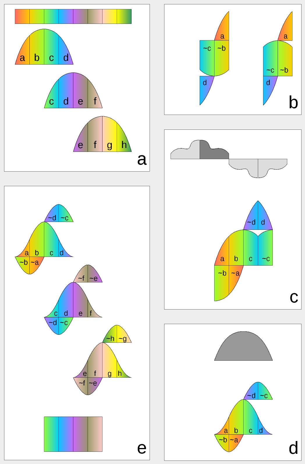
Figure 1. Complex Lapped Transform with DCT-IV/DST-IV: time-domain aliasing cancellation (TDAC) property. a) selection of overlapping input subsequences 2*N-long, multiplication by sine window; b) creating N-long sequences for DCT-IV (left) and DST-IV (right); c) (after frequency domain processing) extending N-long sequence using DCT-IV boundary conditions (DST-IV processing is similar); d) second multiplication by sine window; e) combining partial data
There is another issue related to the space-variant kernels. Fractional pixel shifts are required for multiple steps of the processing: aberration correction (obvious in the case of the lateral chromatic aberration), image rectification before matching that accounts for lens optical distortion, camera orientation mismatch and epipolar geometry transformations. Traditionally it is handled by the image rectification that involves re-sampling of the pixel values for a new grid using some type of the interpolation. This process distorts the signal data and introduces non-linear errors that reduce accuracy of the correlation, that is important for subpixel disparity measurements. Our approach completely eliminates resampling and combines integer pixel shift in the pixel domain and delegates the residual fractional pixel shift (±0.5 pix) to the FD, where it is implemented as a cosine/sine phase rotator. Multiple sources of the required pixel shift are combined for each tile, and then a single phase rotation is performed as a last step of pixel domain to FD conversion.
Frequency Domain Conversion with the Modulated Complex Lapped Transform
Modulated Complex Lapped Transform (MCLT)[3] can be used to split input sequence into overlapping fractions, processed separately and then recombined without block artifacts. Popular application is the signal compression where “processed separately” means compressed by the encoder (may be lossy) and then reconstructed by the decoder. MCLT is similar to the MDCT that is implemented with DCT-IV, but it additionally preserves and allows frequency domain modification of the signal phase. This feature is required for our application (fractional pixel shifts and asymmetrical lens aberrations modify phase), and MCLT includes both MDCT and MDST (that use DCT-IV and DST-IV respectively). For the image processing (2d conversion) four sub-transforms are needed:
- horizontal DCT-IV followed by vertical DCT-IV
- horizontal DST-IV followed by vertical DCT-IV
- horizontal DCT-IV followed by vertical DST-IV
- horizontal DST-IV followed by vertical DST-IV
(more…)