by Oleg Dzhimiev
So far, the code works in the following way:
- Frames from sensor are stored in SDRAM, then the data go to the Cross-Correlation module.
- The output of the C-C module are 256 values for each pass cross-correlation function. The address (=pixel displacement) of the maximal value is written to a BRAM.
- After the whole picture line is processed the results are read out and form a line of a ‘depth frame’ that is sent to the main 353 board.
So, the ‘depth frame’ goes through the 353’s compressor and this makes the data available only for visual analysis. I’m planning:
- 353 will get optionally ‘depth frame’ OR frames from the left/right sensor.
- at the same time the ‘depth frame’ lines will be available through the I2C register – basically that means I’ll just duplicate the BRAM where I store the depth information.
Shall I keep the whole frame? shall I write it to the SDRAM? I’ll use 1 BRAM at first. Section 1 & 2 w/o ‘frames from the left/right sensor‘ will take less then an hour.
by Andrey Filippov
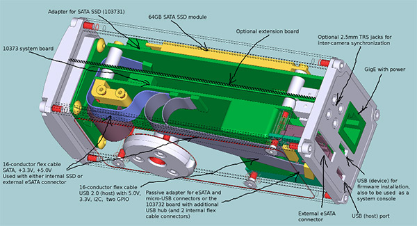
Spent couple days looking if the 10373 board layout can be connected as I hoped. There will be small board with 2 connectors on the back panel (103732) – micro USB and eSATA. In minimal configuration it will be a passive board with connectors only, but there should be some room to add USB hub and a couple internal 10-conductor flex cables for internal USB devices – same as on the 10369 board of the NC353L camera.
SATA and USB signals are split into separate connectors on the 10373 board – that allows to leave USB connected to the back panel adapter while connecting the SATA cable (with additional power) to the internal adapter for the SATA SSD. The image below shows both options, but actually 10373 has only one SATA port so only one SATA device can be connected.
While most functionality of the 10369 board is moved to the main 10373 there is no ports for the inter-camera synchronization – 10369 has 2 sets of oto-isolated synchronization ports – “external” with modular (like telephone) connector for frame-locking several individual cameras an “internal” (with flex cable connectors) for synchronizing multiple camera boards installed in the same enclosure. The synchronization will have to be handled by an extension board that has direct connection to the 18 FPGA I/O pins. The back panel will have holes (covered with plastic overlay when not used) for up to four 2.5mm TRS connectors (like small stereo audio ones). Unfortunately even small 2.5mm TRS plugs plastic bodies are rather large so 2 of them can fit only when connectors are diagonal.. Anyway – that part of the design is not finished yet, we’ll think of something.
Andrey
by Oleg Dzhimiev
1. [In Progress] “Verification of everything”.
The results of running 1 frame through the cross-correlation block are more or less ok now:
- took coefficients’ product bits [31:16] (that is 16 bit rounding)
Sample 1:

Fig.1 Source – test frame.

Fig. 2 Result (there are some errors on the top of the result image near the areas of color change).
Sample 2:
 Fig. 3 The picture from the sensor w/o a lense (a bit dirty – dust on scotch).

Fig. 4 Result, again there are some errors – overflows are possible.
TODO:
1. Adjust the more suitable rounding for fft-coeffs multiplication – perform rounding after multiplication + perform rounding in IFFT?
Current Bits Calculation: 12bits -> FFT(8 stages with rounding) -> 12bits -> MULT(16 bits rounding) -> 8bits -> IFFT(no rounding) -> 16bits.
Try: 12 -> FFT (8 cut) -> 12 -> MULT (8 cut)-> 16 -> IFFT(8 cut) -> 16 – and there should be no errors.
2. Test frames from different channels.
by Andrey Filippov
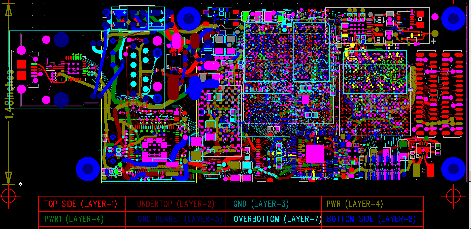
It seems that those additional parts did fit on the board. I still need to restore some power connections and the legend on the board (it is also getting to be a real challenge – the smallest letters have to use 0.125mm (5 mil) lines and there is very little space between the components. It will need some time, but it is definitely doable. This is how the board looks now (click on the image to get the full size):
So to the 10373 features I listed initially in my May, 18 post:
- TMS320DM6467 as the CPU
- Xilinx Spartan 6 FPGA
- 256 MiB NAND flash
- 256 MiB DDR2 system memory
- 256 MiB DDR3 dedicated FPGA memory
- 48V DC over Ethernet cable
- GigE
- USB 2.0 host
- ATA port (to be used with the SATA bridge on the 10369 or similar I/O board)
- USB 1.1 device with micro USB connector. It is connected to the CPU serial port to be used as a system console and alternative boot source
Few more can be added:
- Two sensor ports, each can accommodate existent sensor front ends that work with NC353L cameras. Both sensors will be able to operate at full resolution/speed in parallel.
- SATA port with the flex cable connector. The connector pinout is made so it is possible to use flexible cables (single-layer) , not just 2-layer cable or flex PCB to achieve 100 Ohm impedance for the high-speed differential pairs. On the other end of that cable there will be either eSATA connector on the back panel of the camera or an adapter for the 64GB SSD used in some EEE PC computers. As you can see on Elphel wiki these 64GB memory can easily fit inside the camera – so no more CF cards. Same with 1.8″ HDD – we can make an adapter from the same flex cable – it addition to SATA signals it has both 3.3VDC and 5VDC power.
- Another flex cable connector has USB 2.0 (host) signals, including 5V power and additional 3.3V and 4 GPIO signals from the FPGA. It is possible to put just micro USB connector adapter on the camera back panel (it is likely to be combined with the eSATA one to simplify mounting) or have a 4-port USB hub (similar to the one in the 10369 board) and additional flex-cable connectors for internal USB or I2C internal add-ons (i.e compass).
- Clock/calendar with a super-capacitor power backup, similar to the one in our current 10369A board, but with the additional function – 10373 makes use of the alarm of that clock (it can be set up to a week in the future). Alarm output is used to re-power the camera after it turned itself off (and it can now). DC-DC converters still consume several mA when turned off, but it will be possible to use the camera with a very small solar panel in the wilderness unattended – either periodically recording images to the internal memory or using USB cellular module (if the area has coverage) to upload the images.
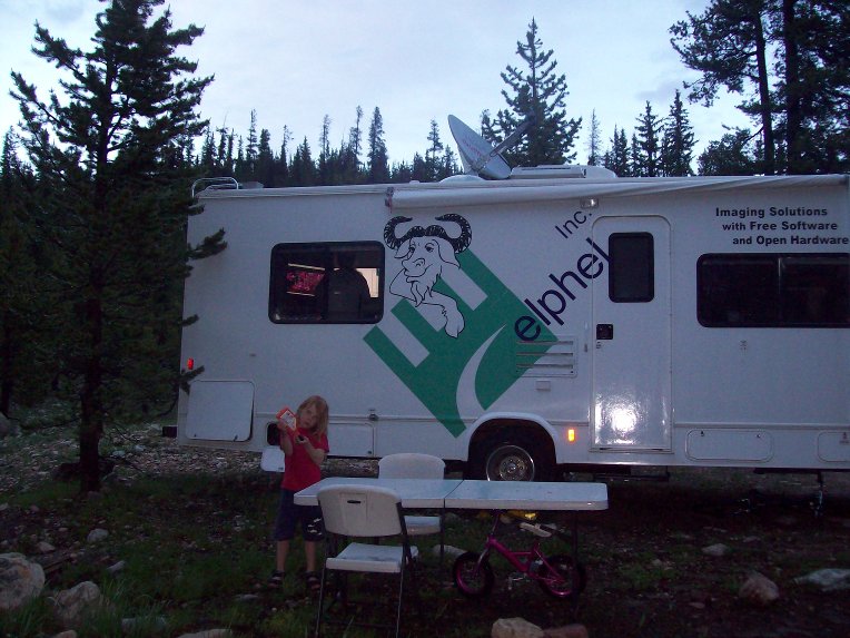
And here is where I’m working on this board – 110.965W 40.65168N. It is raining most of the time – day and night, so I have more time to work.

