3D Perception with Thermal Cameras
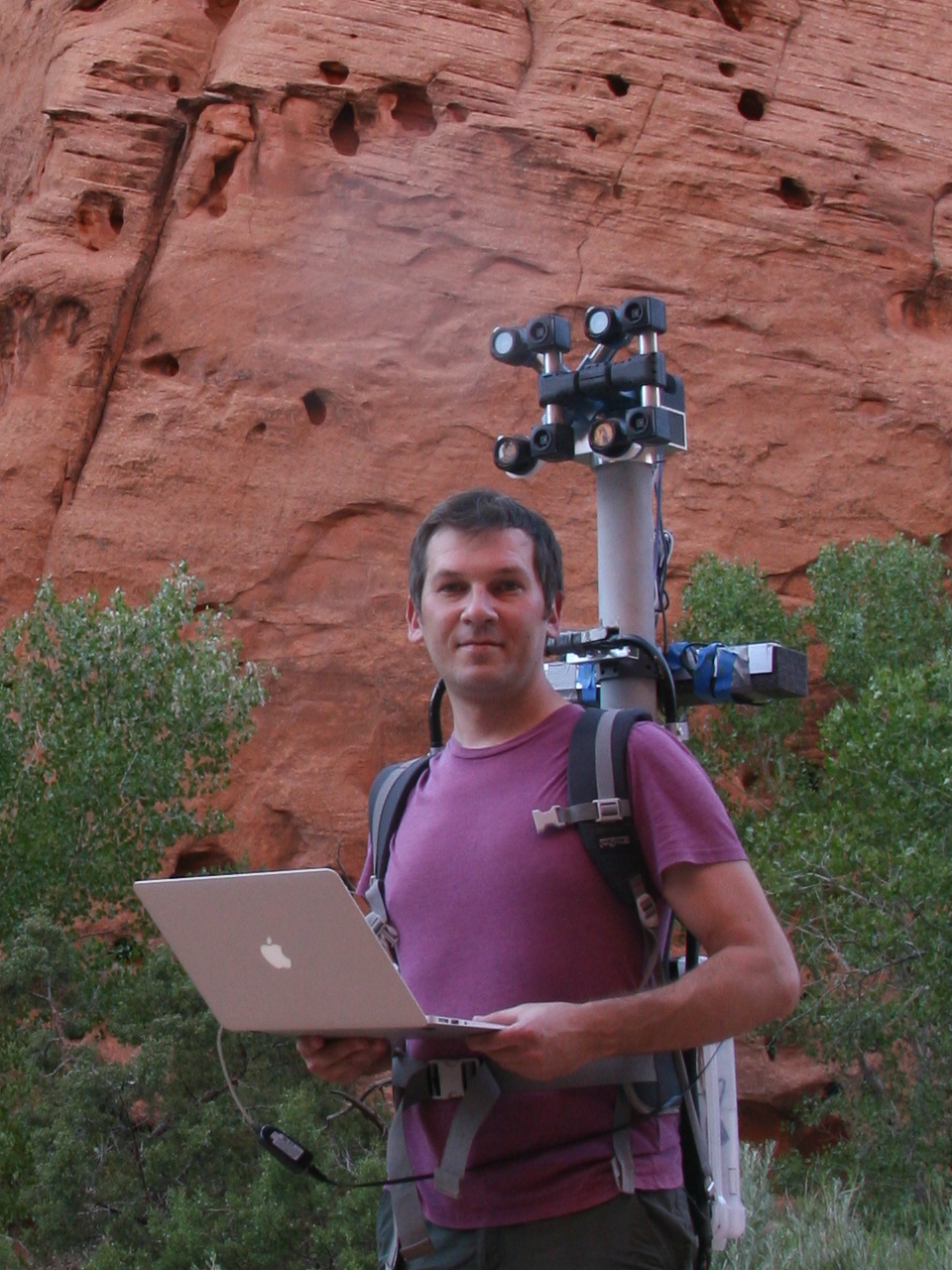
Figure 1. Oleg carrying combined LWIR and visible range camera.
While working on extremely long range 3D visible range cameras we realized that the passive nature of such 3D reconstruction that does not involve flashing lasers or LEDs like LIDARs and Time-of-Flight (ToF) cameras can be especially useful for thermal (a.k.a LWIR – long wave infrared) vision applications. SBIR contract granted at the AF Pitch Day provided initial funding for our research in this area and made it possible.
We are now in the middle of the project and there is a lot of the development ahead, but we have already tested all the hardware and modified our earlier code to capture and detect calibration pattern in the acquired images.
Contents
Printed Calibration Patterns for LWIR
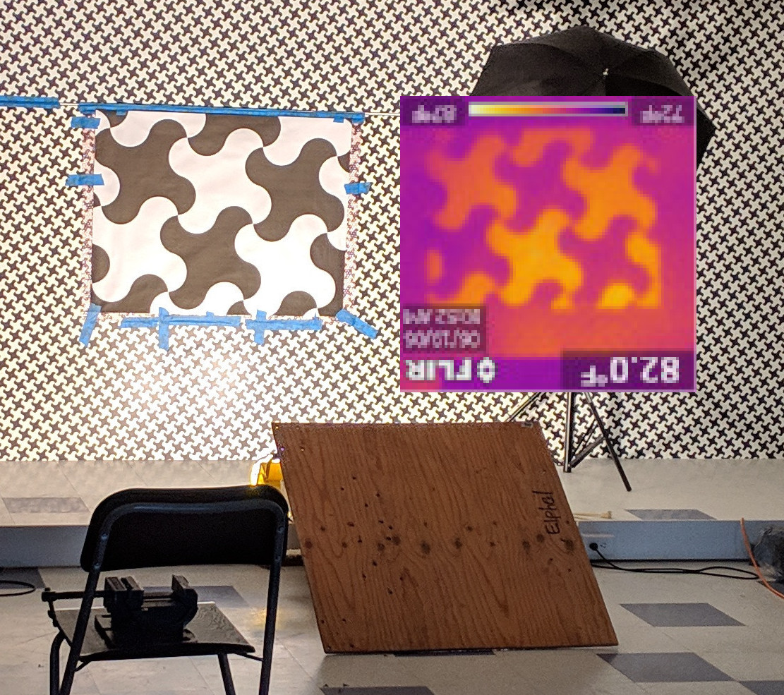
Figure 2. Initial LWIR pattern detection test with a small (100×100 pix) FLIR handheld camera.
For the LWIR imaging we planned to use approach similar to what we have developed for the visible range cameras, and the first step is the precise photogrammetric camera calibration. Before engaging in the project we made sure that we can capture images of the pattern in LWIR wavelength range, the same pattern image should also be registered by the visible range camera to be used as the ground truth data. For the regular cameras there are many ways and materials to create high quality test patterns, our current setup uses 7.0 meters by 3.0 meters pattern printed on five sheets of self-adhesive film attached to the wall. This pattern illuminated by the regular bright fluorescent lamps did not register any image by a LWIR camera (we borrowed a small, handheld FLIR camera, used for HVAC applications).
In the next (successful) test we used a larger scale pattern printed on paper that was not bonded to the wall. The pattern was illuminated by a pair of 500W halogen lamps (see Figure 2). The lamp radiation — both visible and infrared (mostly infrared) was heating the image and so the black painted areas on paper became hotter than the white ones as shown in the FLIR camera image (it is upside down as the camera was held in a vise in that position). The measured temperature difference between white and black areas, illuminated from the distance of 1.5–2 meters was in the range of 2–4°K.
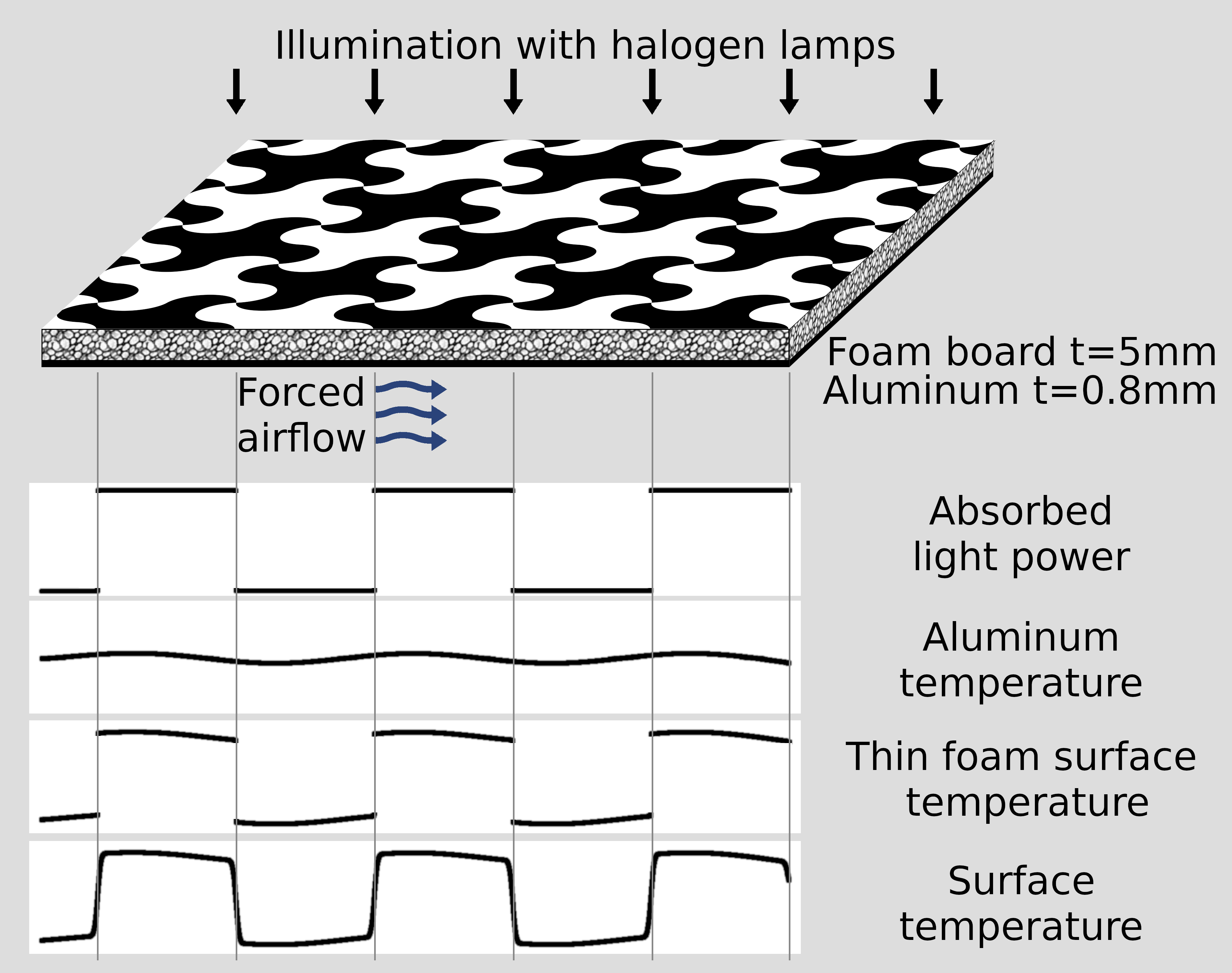
Figure 3. LWIR calibration pattern design.
This quick test proved that with reasonable amount of high power halogen lamps we can achieve sufficient temperature contrast for the photogrammetric calibration. It still has some limitations — while the amount of heat absorbed by the pattern paint can be calculated from the data registered by the visible range cameras, the pattern surface temperature also depends on less controlled effects – air convection and heat transfer to the wall where the paper touches it. These factors reduce accuracy of the calibration, to mitigate their influence we designed a pattern where the ground truth relative surface temperature can be calculated from the measured visible range images and a few parameters that describe thermal properties of the materials.
Calibration Pattern Design
We used 5mm thick presentation type foam boards that consist of the polystyrene foam layer between two paper surface sheets. As we found out later, it is important to use both black and white paints during the printing process – unpainted paper surface that looks matte in visible light behaves like a mirror for the LWIR radiation and reflects the lamps used for illumination. You may find such reflection in Figure 5 – the leftmost panel that was built first does not have white paint. A thin (t=0.8 mm) aluminum sheets are glued to the back surfaces of the foam boards, and the forced airflow equalizes their temperatures. Figure 4 reveals the back side of the pattern module – thicker (1/2″ and 1″) machined foam boards make ribs that provide structural integrity of the pattern modules. These ribs are attached to the aluminum side of the pattern sheets with epoxy resin, their other side is reinforced with the fiberglass tape. Soft foam along the perimeter of the modules allows another use of the fans that provide the forced airflow – the developed vacuum is used to firmly press the modules to the smooth (covered with the visible range pattern film) wall. Timelapse video below illustrates the process of building and installation of the LWIR calibration pattern.
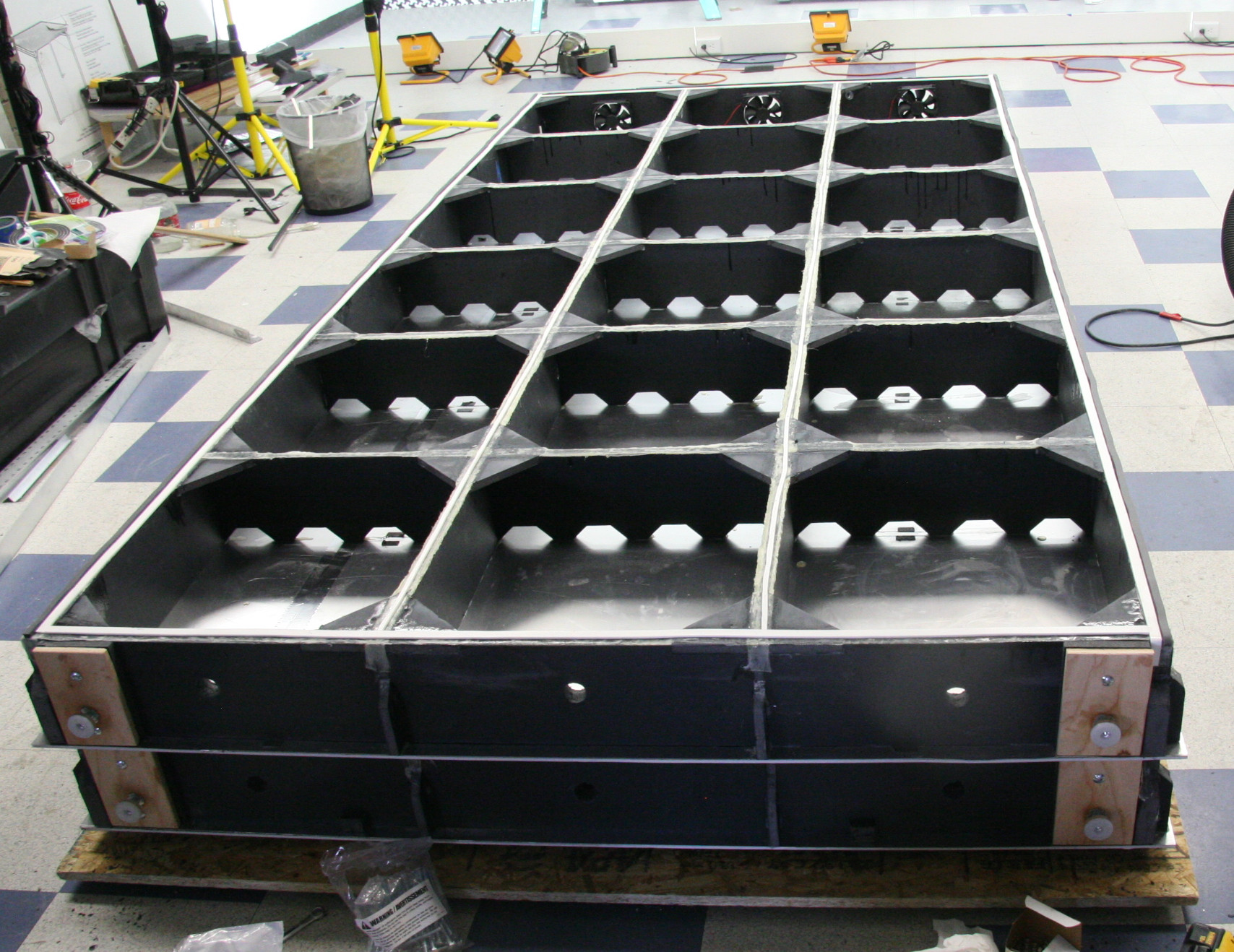
Figure 4. A stack of two face-down LWIR pattern modules.
Figure 3 illustrates temperature calculation for the uniformly illuminated pattern, this method will be used to derive ground truth thermal data from the registered visible range images. For a straight line on a surface of the pattern the absorbed light power produces a step function. The temperature of the underlying aluminum is a blurred version of that function, with the sigma depending on the thicknesses and thermal conductivity ratios of the foam and aluminum. With the used parameters amplitude of the aluminum temperature variations is below 1%. For the very thin foam the surface temperature would be just a sum of the aluminum temperature and a step function, the actual surface temperature distribution is blurred by the amount proportional to the foam thickness as the heat flow under the black/white pattern borders is not exactly orthogonal to the surface.
Calibration pattern period is 357mm, approximately four times larger than that of the pattern we use for the visible range cameras calibration. This size is selected to work with the low resolution prototype system (160×120 pix in each of the four channels) and still is suitable for the higher resolution LWIR imagers of up to 1280×960. Figure 5 shows the view of the pattern by the visible range (left) and LWIR (right) cameras from the distance of 3 meters (top) and 7 meters (bottom) from the target. The field of view of the already calibrated visible range cameras is slightly larger that that of the LWIR, so ground truth data is available over all LWIR sensors area.
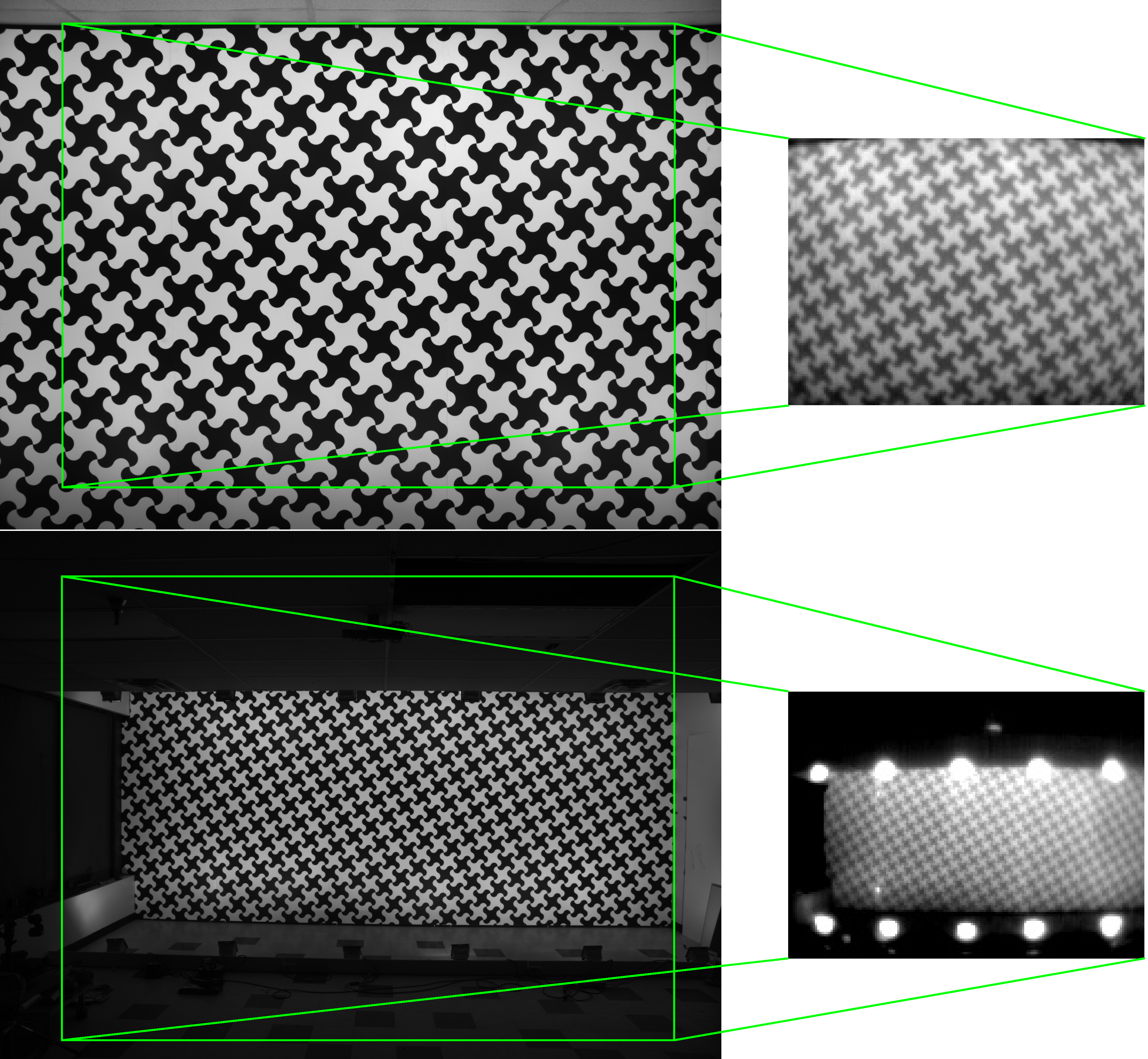
Figure 5. LWIR calibration pattern captured by visible range (2592×1936) and LWIR (160×120) cameras from the distance of 3 meters (above) and 7 meters (below).
Visible + LWIR combo camera
The main goal of our current project is to determine to what extent methods that we currently use for visible range camera photogrammetric calibration, distortion and aberration correction, deep subpixel disparity calculation and neural network training are applicable to the LWIR systems. Generally LWIR sensors have lower resolution than the regular visible and near infrared (VNIR) ones, are expensive and subject to export control, so with the limited time and resources available we selected small (160×120) FLIR Lepton-3.5 sensor modules available at Digi-Key. These modules have integrated germanium lenses and mechanical shutters that are essential for the photometric calibration. The sensors have limited frame rate (9 FPS) that puts them outside of the scope of export regulations. We plan use higher resolution sensors after evaluating the prototype system and achieving the goal of 0.1 pix (or better) disparity resolution.
The overall prototype camera design (Figure 6) is rather straightforward: we used already calibrated X-shaped quad camera and added another one with four LWIR sensors. FLIR Leton-3.5 modules do not support externally triggered operation, so I hoped that if all 4 sensors are fed with the same clock, and the reset signal is de-asserted simultaneously, then all channels will stay in sync and output frames simultaneously. Later this assumption turned out to be true, the difference between the channels after startup was in the range of ±10μs and it did not change over time. These small offset values are likely related to the analog PLL lock, they do not require any additional correction as they are more than a thousand times shorter than the effective pixel integration time. The visible range quad camera is triggered by the LWIR one. We measured internal LWIR module latency by capturing image of the rotating object and used this data to program the cameras triggering parameters to achieve simultaneous image capturing by all 8 of the visible range and thermal sensors.
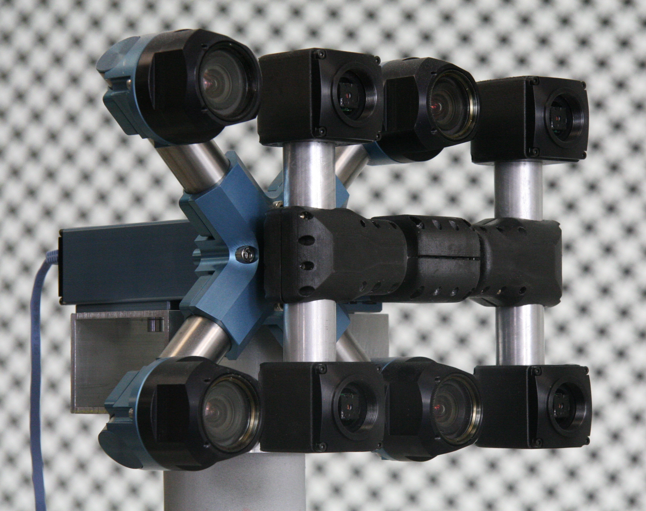
Figure 6. Prototype combo camera: 4×VNIR+4×LWIR
Lepton-3.5 sensor module is small enough so we were able to fit it together with the power conditioning circuitry and the configuration EEPROM on the same dimension PCB as our regular sensor front ends (SFE) of 28mm×15mm and then mount in the standard SFE body. The board electrical and mechanical design is documented in Elphel Wiki.
Lepton module is controlled over the I2C bus that was already supported in Elphel NC393 series cameras, the video output is provided over SPI-based VoSPI interface, so some FPGA development along with the related drivers and applications code was required. Due to the digitized microbolometers output instead of that of a photodiodes in regular CMOS sensors, the rationale behind the use of the gamma compression that allows virtually lossless 8-bit representation of 12-bit pixel ADC output does not hold. That in turn required full 16-bit output rather than the JP4 image format that we were using for over a decade. We implemented Tiff format (both 8 and 16 bits per pixel) that is now available for all other supported image sensors, not only for the LWIR ones.
Photogrammetric calibration software
We are now working on adapting our existing code base to work with the LWIR low resolution sensors, and the photogrammetric calibration is the first step before we can perform 3D scene reconstruction and train a DNN to get higher disparity measurement accuracy. Our existing calibration workflow consists of the following steps:
- Capturing of a few hundred image sets of the calibration pattern from a 3 different camera locations, using switchable laser pointers for absolute matching of the periodic pattern cells in the camera images.
- Extracting pattern grid key points positions in the individual images with deep subpixel accuracy (0.03-0.05 pix) combining both pixel domain and frequency domain image processing.
- Bundle adjustment of the camera intrinsic and extrinsic parameters assuming lenses radial distortion models, physical pattern grid points correction with Levenberg-Marquardt algorithm (LMA).
- Continuing bundle adjusting allowing non-radial lens distortions and perform photometric calibration of the sensors (flat field, lens vignetting correction).
- Applying calculated distortions to the synthesized pattern grid and calculating Point Spread Function (PSF) to be used for space-variant deconvolution for aberration correction.
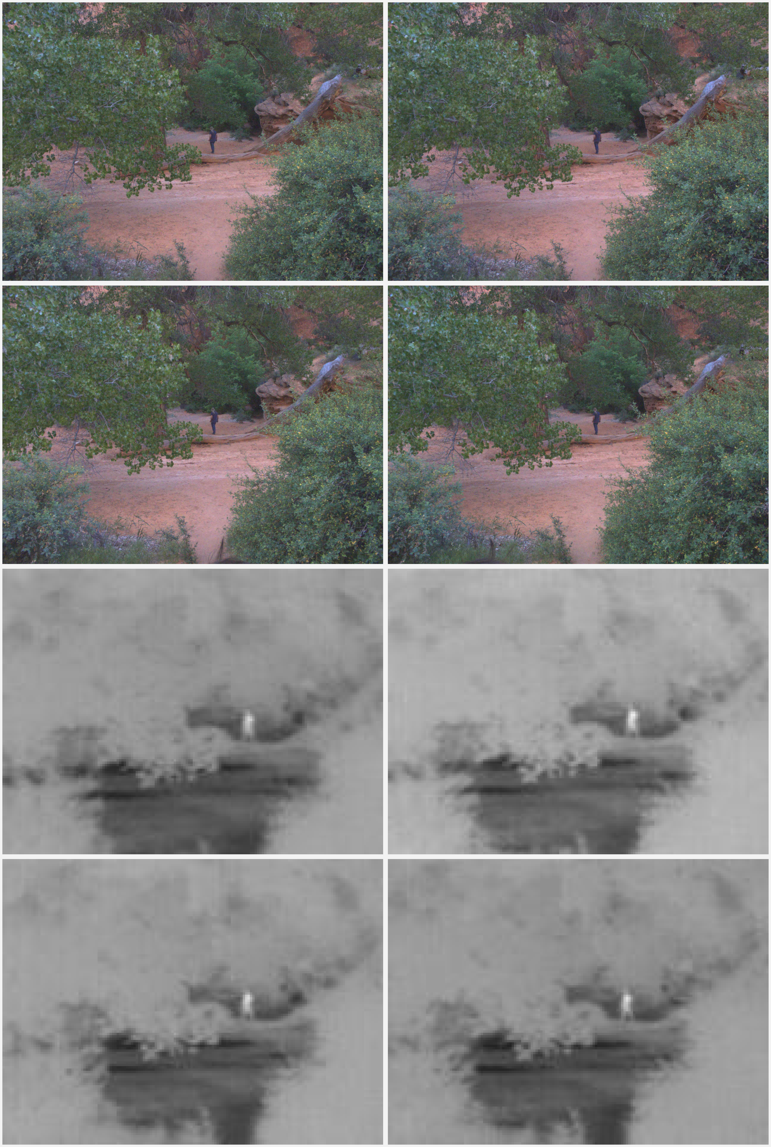
Figure 7. Image set of 4 color and 4 LWIR images from the frame sequence captured by Talon camera (raw images – not rectified/matched).
As of now we just finished adaptation/re-implementation of the first two steps to work with LWIR sensors. Compared to the above workflow we do not use laser pointers for LWIR, but the visible range quad camera is already calibrated and can provide absolute matching of the pattern images. The major challenge in step 2 was to make the software work when there are very few (or only one) pattern cell available in each processing window – our previously developed software could comfortably use many pattern cells.
3D perception with LWIR
When the remaining steps of the photogrammetric calibration will be finished, we will use the quad camera 3D scene reconstruction software to build the 3D scenes from the captured LWIR images. The paired visible range quad camera has significantly higher resolution and its disparity data will be used as ground truth for the network training. Here we will benefit from the thermal imaging difference from the traditional image intensifier-based night vision cameras that can only operate in very low light conditions. LWIR sensors can operate simultaneously with the visible range ones (and many systems fuse their images to effectively enhance LWIR resolution).
Impatient to get real life scene imagery even before the software is ready, we took the first prototype camera to Southern Utah. We call this prototype “Talon” for the T-38 training jet where the visible range quad camera plays the role of the instructor that sits slightly behind the LWIR “the student”. We captured synchronized visible/LWIR images in a slot canyon as well as the LWIR-only sets in the pitch black darkness — it was a New Moon that night.
The raw LWIR images themselves do not look that exciting – there are many much higher resolution ones used by the military, law enforcement and even hunters. The things will change when we’ll be able to generate the LWIR 3D scenes.
Leave a Reply