March 11, 2011
by Oleg Dzhimiev
Both, Google Maps API and Open Layers API, are quite simple, though it can take some time to find a perfect example. The maps are added to the WebGL panorama view test page (read “Experimenting with WebGL panoramas”)
(more…)
December 2, 2009
by Oleg Dzhimiev
Rewrote some blocks of the code for the 10359’s fpga and at last found out what was the problem in the alternation mode with buffering – it was the delay between the frames that were sent to the 10353 – it was too small. I used a counter earlier for that but it had 16 bits and that wasn’t enough. I extended it to 32 bits and succeeded with the delay about 220 clk tacts (220x~10ns = ~ 10ms – this is a bit much but I’m not sure – probably missing something in frame generation).
Andreas has recently advised to add a mode where the alternating frames are combined into one to make it easier to say which frame belongs to which sensor. I coded the first version with simple buffering but didn’t test much. Some notes:
- 2 frames are combined vertically.
- the initial (resulting frame) resolution is set from the camera interface (camvc).
- the sensors are programmed to half vertical size and the camvc doesn’t know about it.
I also updated the 10359 interface to switch between these modes and to change other settings.
It is worth mentioning that after ‘automatic phases adjustment’ from 10359’s interface sensors have different color gains in their registers. So, there’s a need to reprogram this parameters after phase adjustments.
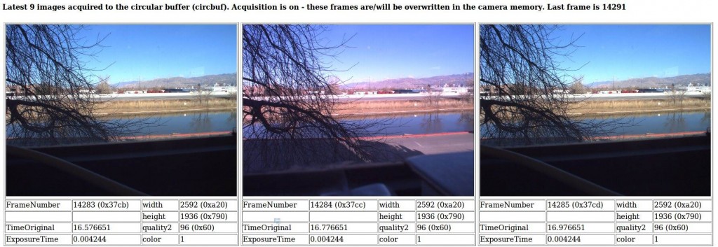
What we’ve got now working in the 10359 is:
1. Alternation mode with (or without) buffering in 10359’s DDR SDRAM:
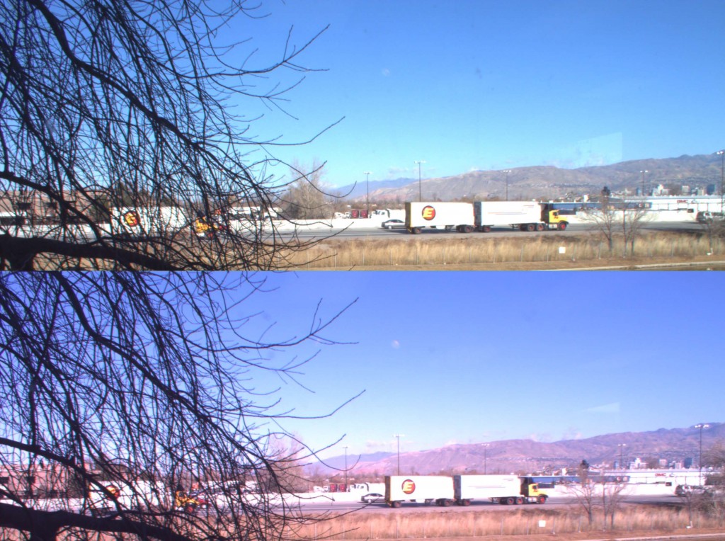
2. Alternation mode with combined buffered frames:
TODO:
1. Make sensors programmed identically after phase adjusment.
2. Add stereo module
September 29, 2009
by Oleg Dzhimiev
The modes are:
- Direct alternating channels mode.
At first, I rewrote the logic of switching from what I already had and this resulted in parsedit.php “Error 500” and the streamer stop (when the sensors were in the free run mode, in triggered – everything was ok) while it was everything fine with the testbench. Coudn’t find what is wrong for sometime. Part of the logic was based on sync signals levels and under certain conditions the switching didn’t work – the error was corrected by using only the sync signals edges.
 Fig.1 A sample frame in the testbench is 2592×3 (to reduce verification time), “ivact” – vertical sync signal, “ihact” – horizontal sync signal, “pxdr” – pixel data. White numbers in ‘ivact’ line represent an appropriate channel.
- Alternating channels – one channel direct, another – bufferred.
With this mode the situation was almost the same as with the previous mode – the same changes but the frame from the second channel, the one that is buffered looks brighter, but if to disable the first channel – the buffered frame is correct:
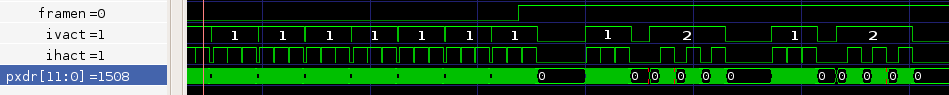 Fig.2 “framen” – frame enable register, allows work when ‘high’.

Fig.3 Good direct frame (left) and ‘whitened’ buffered frame (right). Probably some signal’s latencies are incorrect.
Is separate due to the problems with other two modes. It’s being added currently.
I’m also making the project less messy, optimizing registers addresses and rewriting scripts to make the work with 10359 easier.
August 28, 2009
by Oleg Dzhimiev
Notes:
- Commands can be ‘broadcasted’ through I2C to all the sensors.
- Sensors work only in snapshot (external trigger) mode – to have them configured identically.
- Depth frame mode.
- Direct alternating channels mode.
- Alternating channels – one channek direct, another – bufferred.
August 14, 2009
by Oleg Dzhimiev
There’s a nice page on Elphel’s wiki describes the problem: Adjusting sensor clock phase (the last paragraph is outdated, the script is in the ‘attic’, and I couldn’t find an alternative in the new 8.x firmware).
It was difficult to adjust data phases for long cables (& sometimes even for short) connecting sensor boards with 10359. To do it in a more or less automatic way a php script ‘test_inner_10359.php’ is used, which in its turn uses ‘phases_adjust.php’ with 5 phase steps at a time and compares the MD5 sums of the frames with the known one at defined sensor parameters.
So far, the solution is:
- The problem was with the sensor on J2 mostly. In 10359 project that sensor is clocked through the BUFG (idclk) by the clock coming from 10353 (DCLK) . After inverting it the things got better – and this is luck.
- In ‘phases_adjust.php” changed the number of phase steps taken from 5 to 2 to increase the precision. And it worked =) – 5/5 for the camera in the office.
TODO:
- Add an “AUTO” button to 10359 interface page.
- Modify standard (in prod353) ‘test_inner_10359.php’ to be able to work with only 2 sensors.
HOWTO:
- go to: http://<camera-ip>/359/10359_controls.html
PS: Also tried to add a bit mask to data bus from the sensor just to find out whether the data bus changing time exceeds the period but the picture became unstable every time the phase was close to the correct one.
July 15, 2009
by Oleg Dzhimiev
So far, the code works in the following way:
- Frames from sensor are stored in SDRAM, then the data go to the Cross-Correlation module.
- The output of the C-C module are 256 values for each pass cross-correlation function. The address (=pixel displacement) of the maximal value is written to a BRAM.
- After the whole picture line is processed the results are read out and form a line of a ‘depth frame’ that is sent to the main 353 board.
So, the ‘depth frame’ goes through the 353’s compressor and this makes the data available only for visual analysis. I’m planning:
- 353 will get optionally ‘depth frame’ OR frames from the left/right sensor.
- at the same time the ‘depth frame’ lines will be available through the I2C register – basically that means I’ll just duplicate the BRAM where I store the depth information.
Shall I keep the whole frame? shall I write it to the SDRAM? I’ll use 1 BRAM at first. Section 1 & 2 w/o ‘frames from the left/right sensor‘ will take less then an hour.
July 9, 2009
by Oleg Dzhimiev
1. [In Progress] “Verification of everything”.
The results of running 1 frame through the cross-correlation block are more or less ok now:
- took coefficients’ product bits [31:16] (that is 16 bit rounding)
Sample 1:

Fig.1 Source – test frame.

Fig. 2 Result (there are some errors on the top of the result image near the areas of color change).
Sample 2:
 Fig. 3 The picture from the sensor w/o a lense (a bit dirty – dust on scotch).

Fig. 4 Result, again there are some errors – overflows are possible.
TODO:
1. Adjust the more suitable rounding for fft-coeffs multiplication – perform rounding after multiplication + perform rounding in IFFT?
Current Bits Calculation: 12bits -> FFT(8 stages with rounding) -> 12bits -> MULT(16 bits rounding) -> 8bits -> IFFT(no rounding) -> 16bits.
Try: 12 -> FFT (8 cut) -> 12 -> MULT (8 cut)-> 16 -> IFFT(8 cut) -> 16 – and there should be no errors.
2. Test frames from different channels.
June 23, 2009
by Oleg Dzhimiev
1. [In Progress] “Verification of everything”
Images below show the results of tests on 10359 board. Fig.2 represents the displacement map multiplied by 128 – {dires_data_out[4:0],7’b0}. The correct resulting image should be black as the maximum of the correlation function must be in 0. Checked the results in simulation – they are the same. Verifying.

Fig. 1 Input image, same image comes from the 2nd channel (Left=Right).

Fig. 2. Result image (incorrect)
June 16, 2009
by Oleg Dzhimiev
1. [Done] Finish with the “full_pages_in_buffer“. Made more convenient to me and corrected the error I had done before (double write request from channel).
2. [In Progress] Verification of everything.
Currently instead of black frames I get different ones (apparently, something’s wrong: black vertical lines after each 1024 pixels) – checking the simulation:
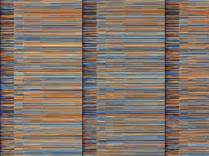
Fig. 1 Test image, size 2592×1940
TODO:
1. Verification.
2. I also didn’t implemented multiplication on the Hamming function before performing the FFTs.
June 1, 2009
by Oleg Dzhimiev
1. [Done] Simulation of data path of Cross-Correlation (C-C) module.
2. [Done] Integration of the C-C block to x359.
3. [In Progress] Simulation of the C-C and x359 as a whole.
3.a. [Done] Set up memory controller.
- Write length is set to 64(8×8) words.
- Fixed image size to 2592×1944.
- C-C block is set to work with 512 words, reading out 256 word at a time with overlapping – 3 256-word reads till another command to the C-C block.
3.b. [Done] Simulate for 1 write and 1 read channels. Here there are no competetive requests from 2 write channels.
3.c. [In Progress] Simulate for 2 write and 2 read channels.
- Fixed reg “full_pages_in_buffer” correct work. It was commented earlier by me as I used only one channel at a time to access SDRAM.
- For write channels – changed reg “full_pages_in_buffer” size to 32 (page size is 64). And if it reaches the maximum then a aditional BRAM is neaded.
TODO:
1. Finish with the “full_pages_in_buffer“.
2. Make an x359.bit and check the work with the whole frame.
3. I also didn’t implemented multiplication on the Hamming function before performing the FFTs.
« Previous Page —
Next Page »