March 18, 2016
by Andrey Filippov
We added the AHCI SATA controller Verilog code to the rest of the camera FPGA project, together they now use 84% of the Zynq slices. Building the FPGA bitstream file requires proprietary tools, but all the simulation can be done with just the Free Software – Icarus Verilog and GTKWave. Unfortunately it is not possible to distribute a complete set of the files needed – our code instantiates a few FPGA primitives (hard-wired modules of the FPGA) that have proprietary license.
Please help us to free the FPGA devices for developers by re-implementing the primitives as Verilog modules under GNU GPLv3+ license – in that case we’ll be able to distribute a complete self-sufficient project. The models do not need to provide accurate timing – in many cases (like in ours) just the functional simulation is quite sufficient (combined with the vendor static timing analysis). Many modules are documented in Xilinx user guides, and you may run both the original and replacement models through the simulation tests in parallel, making sure the outputs produce the same signals. It is possible that such designs can be used as student projects when studying Verilog.
(more…)
March 14, 2016
by Mikhail Karpenko
AHCI PLATFORM DRIVER
In kernels prior to 2.6.x AHCI was only supported through PCI and hence required custom patches to support platform AHCI implementation. All modern kernels have SATA support as part of AHCI framework which significantly simplifies driver development. Platform drivers follow the standard driver model convention which is described in Documentation/driver-model/platform.txt in kernel source tree and provide methods called during discovery or enumeration in their platform_driver structure. This structure is used to register platform driver and is passed to module_platform_driver() helper macro which replaces module_init() and module_exit() functions. We redefined probe() and remove() methods of platform_driver in our driver to initialize/deinitialize resources defined in device tree and allocate/deallocate memory for driver specific structure. We also opted to resource-managed function devm_kzalloc() as it seems to be preferred way of resource allocation in modern drivers. The memory allocated with resource-managed function is associated with the device and will be freed automatically after driver is unloaded.
(more…)
March 12, 2016
by Andrey Filippov
Implementation includes AHCI SATA host adapter in Verilog under GNU GPLv3+ and a software driver for GNU/Linux running on Xilinx Zynq. Complete project is simulated with Icarus Verilog, no encrypted modules are required.
This concludes the last major FPGA development step in our race against finished camera parts and boards already arriving to Elphel facility before the NC393 can be shipped to our customers.
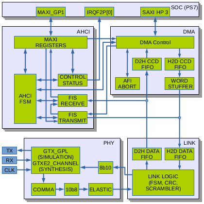
Fig. 1. AHCI Host Adapter block diagram
Why did we need SATA?
Elphel cameras started as network cameras – devices attached to and controlled over the Ethernet, the previous generations used 100Mbps connection (limited by the SoC hardware), and NC393 uses GigE. But this bandwidth is still not sufficient as many camera applications require high image quality (compared to “raw”) without compression artifacts that are always present (even if not noticeable by the human viewer) with the video codecs. Recording video/images to some storage media is definitely an option and we used it in the older camera too, but the SoC IDE controller limited the recording speed to just 16MB/s. It was about twice more than the 100Mb/s network, but still was a bottleneck for the system in many cases. The NC393 can generate 12 times the pixel rate (4 simultaneous channels instead of a single one, each running 3 times faster) of the NC353 so we need 200MB/s recording speed to keep the same compression quality at the increased maximal frame rate, higher recording rate that the modern SSD are capable of is very desirable.
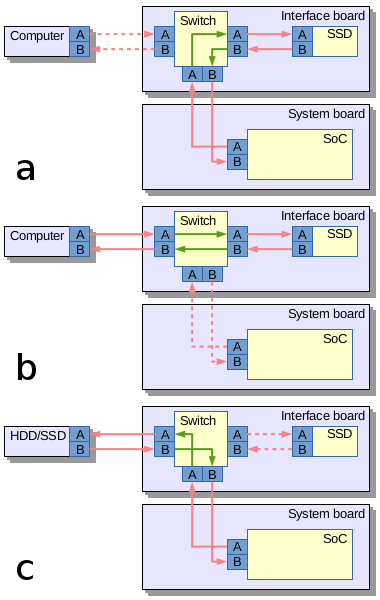
Fig.2. SATA routing: a) Camera records data to the internal SSD; b) Host computer connects directly to the internal SSD; c) Camera records to the external mass storage device
The most universal ways to attach mass storage device to the camera would be USB, SATA and PCIe. USB-2 is too slow, USB-3 is not available in Xilinx Zynq that we use. So what remains are SATA and PCIe. Both interfaces are possible to implement in Zynq, but PCIe (being faster as it uses multiple lanes) is good for the internal storage while SATA (in the form of eSATA) can be used to connect external storage devices too. We may consider adding PCIe capability to boost recording speed, but for initial implementation the SATA seems to be more universal, especially when using a trick we tested in Eyesis series of cameras for fast unloading of the recorded data.
Routing SATA in the camera
It is a solution similar to USB On-The-Go (similar term for SATA is used for unrelated devices), where the same connector is used to interface a smartphone to the host PC (PC is a host, a smartphone – a device) and to connect a keyboard or other device when a phone becomes a host. In contrast to the USB cables the eSATA ones always had identical connectors on both ends so nothing prevented to physically link two computers or two external drives together. As eSATA does not carry power it is safe to do, but nothing will work – two computers will not talk to each other and the storage devices will not be able to copy data between them. One of the reasons is that two signal pairs in SATA cable are uni-directional – pair A is output for the host and input for device, pair B – the opposite.
Camera uses Vitesse (now Microsemi) VSC3304 crosspoint switch (Eyesis uses larger VSC3312) that has a very useful feature – it has reversible I/O ports, so the same physical pins can be configured as inputs or outputs, making it possible to use a single eSATA connector in both host and device mode. Additionally VSC3304 allows to change the output signal level (eSATA requires higher swing than the internal SATA) and perform analog signal correction on both inputs and outputs facilitating maintaining signal integrity between attached SATA devices.
Aren’t SATA implementations for Xilinx Zynq already available?
Yes and no. When starting the NC393 development I contacted Ashwin Mendon who already had SATA-2 working on Xilinx Virtex. The code is available on OpenCores under GNU GPL license. There is an article published by IEEE . The article turned out to be very useful for our work, but the code itself had to be mostly re-written – it was still for different hardware and were not able to simulate the core as it depends on Xilinx proprietary encrypted primitives – a feature not compatible with the free software simulators we use.
Other implementations we could find (including complete commercial solution for Xilinx Zynq) have licenses not compatible with the GNU GPLv3+, and as the FPGA code is “compiled” to a single “binary” (bitstream file) it is not possible to mix free and proprietary code in the same design.
(more…)
February 11, 2016
by Olga Filippova
The components for 10393 and other related circuit boards for the new NC393 camera series have been ordered and contract manufacturing (CM) is ready to assemble the first batch of camera boards.
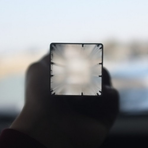
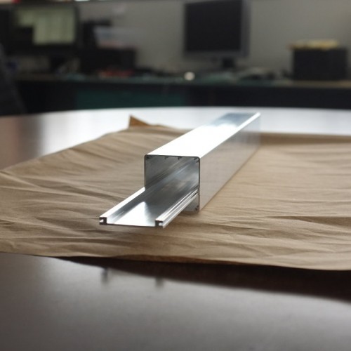
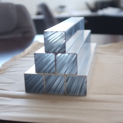
In the meantime, the extruded parts that will be made into NC393 camera body have been received at Elphel. The extrusion looks very slick with thin, 1mm walls made out of strong 6061-T6 aluminium, and weighs only 55g. The camera’s new lightweight design is suitable for use on a small aircraft. The heat frame responsible for cooling the powerful processor has also been extruded.
We are very pleased with the performance of Profile Precision Extrusions located in Phoenix, Arizona, which have delivered a very accurate product ahead of the proposed schedule. Now we can proudly engrave “Made in USA” on the camera, as now even the camera body parts are made in the United States.
Of course, we have tried to order the extrusion in China, but the intricately detailed profile is difficult to extrude and tolerances were hard to match, so when Profile Precision was recommended to us by local extrusion facilities we were happy to discover the outstanding quality this company offers.
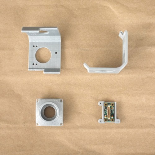
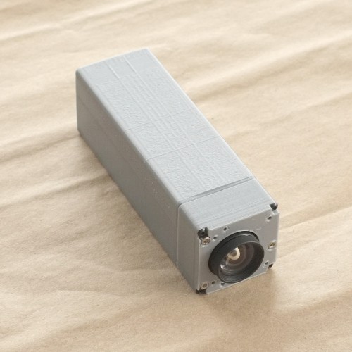
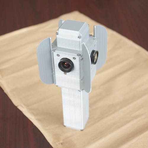
While waiting for the extruded parts we have been playing with another new toy: the 3D printer. We have been creating prototypes of various camera models of the NC393 series. The cameras are designed and modelled in a 3D virtual environment, and can viewed and even taken apart by mouse click thanks to X3dom technology. The next step is to build actual parts on the 3D printer and physically assemble the camera prototypes, which will allow us to start using the prototypes in the physical world: finding what features are missing, and correcting and finalizing the design. For example, when the mini-panoramic NC393-4PI4 camera prototype was assembled it was clear that it needs the 4 fins (now seen on the final model) to protect the lenses from touching the surfaces as well as to provide shade from the sun. NC393-4PI4 and NC393-4PI4-IMU-GPS are small 360 degree panoramic cameras assembled with 4 fish-eye lenses especially suitable for interior panoramic applications.
The prototypes are not as slick as the actual aluminium bodies, but they give a very good example of what the actual cameras will look like.
As of today, the 10393 and other boards are in production, the prototypes are being built and tested for design functionality, and the aluminium extrusions have been received. With all this taken care of, we are now less than one month away from the NC393 being offered for sale; the first cameras will be distributed to the loyal Elphel customers who have placed and pre-paid orders several weeks ago.
December 21, 2015
by Andrey Filippov
Converting mechanical assemblies to X3D models from STEP (ISO 10303) files
Like all manufacturing companies we use mechanical CAD program to design our products. We would love to use Free Software programs for that, but so far even FreeCAD has a warning on their download page “FreeCAD is under heavy development and might not be ready for production use”. We have to use proprietary tools, our choice was the program that natively runs on GNU/Linux we use on our computers. This program generates STEP files that we can send to virtually any machine shop (locally or overseas) and expect to receive the manufactured parts that match our design. For the last 6 years we kept the CAD models for all the camera parts on Elphel Wiki hoping they might be needed not only by the machine shops we order parts from, but also by our users to incorporate (or modify) our products in their systems.
(more…)
November 12, 2015
by Andrey Filippov
Sensors (ON Semiconductor MT9F002) and blank PCBs arrived in time and so I was able to hand-assemble two 10398 boards and start testing them. I had some minor problems getting data output from the first board, but it turned out to be just my bad soldering of the sensor, the second board worked immediately. To my surprise I did not have any problems with HiSPi decoder that I simulated using the sensor model I wrote myself from the documentation, so the color bar test pattern appeared almost immediately, followed by the real acquired images. I kept most of the sensor settings unmodified from the default values, just selected the correct PLL multiplier, output signal levels (1.8V HiVCM – compatible with the FPGA) and packetized format, the only other registers I had to adjust manually were exposure and color analog gains.
As it was reasonable to expect, sensitivity of the 14MPix sensor is lower than that of the 5MPix MT9P006 – our initial estimate is that it is 4 times lower, but this needs more careful measurements to find out exposure required for pixel saturation with the same illumination. Analog channel gains for both sensors we set slightly higher than minimal ones for the saturation, but such rough measurements could easily miss a factor of 1.5. MT9F002 offers more controls over the signal chain gains, but any (even analog) gain in the chain that boosts signal above the minimal needed for saturation proportionally reduces used “well capacity”, while I expect the Full Well Capacity (FWC) is already not very high for the 1.4μm x1.4 μm pixel sensor. And decrease in the number of electrons stored in a pixel accordingly increases the relative shot noise that reveals itself in the highlight areas. We will need to accurately measure FWC of the MT9F002 and have better sensitivity comparison, including that of the binned mode, but I expect to find out that 5MPix sensor are not obsolete yet and for some applications may still have advantages over the newer sensors.
(more…)
November 4, 2015
by Andrey Filippov
All the PCBs for the new camera: 10393, 10389 and 10385 are modified to rev “A”, we already received the new boards from the factory and now are waiting for the first production batch to be build. The PCB changes are minor, just moving connectors away from the board edge to simplify mechanical design and improve thermal contact of the heat sink plate to the camera body. Additionally the 10389A got m2 connector instead of the mSATA to accommodate modern SSD.
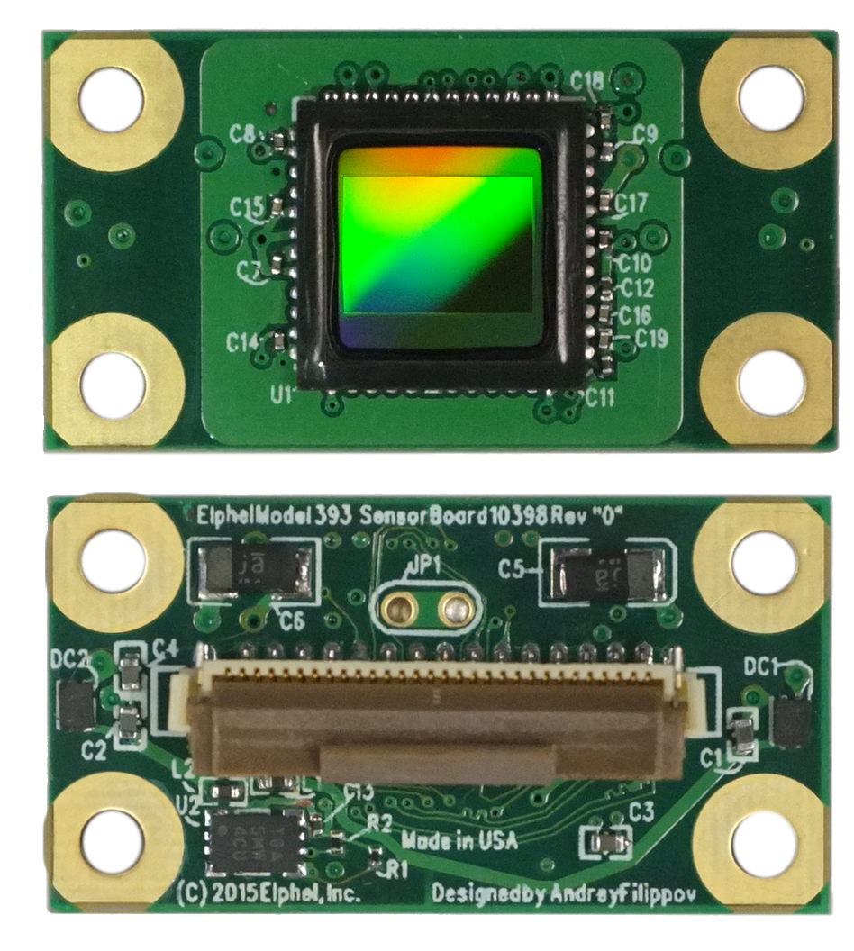
While waiting for the production we designed a new sensor board (10398) that has exactly the same dimensions, same image sensor format as the current 10338E and so it is compatible with the hardware for the calibrated sensor front ends we use in photogrammetric cameras. The difference is that this MT9F002 is a 14 MPix device and has high-speed serial interface instead of the legacy parallel one. We expect to get the new boards and the sensors next week and will immediately start working with this new hardware.
(more…)
September 18, 2015
by Andrey Filippov
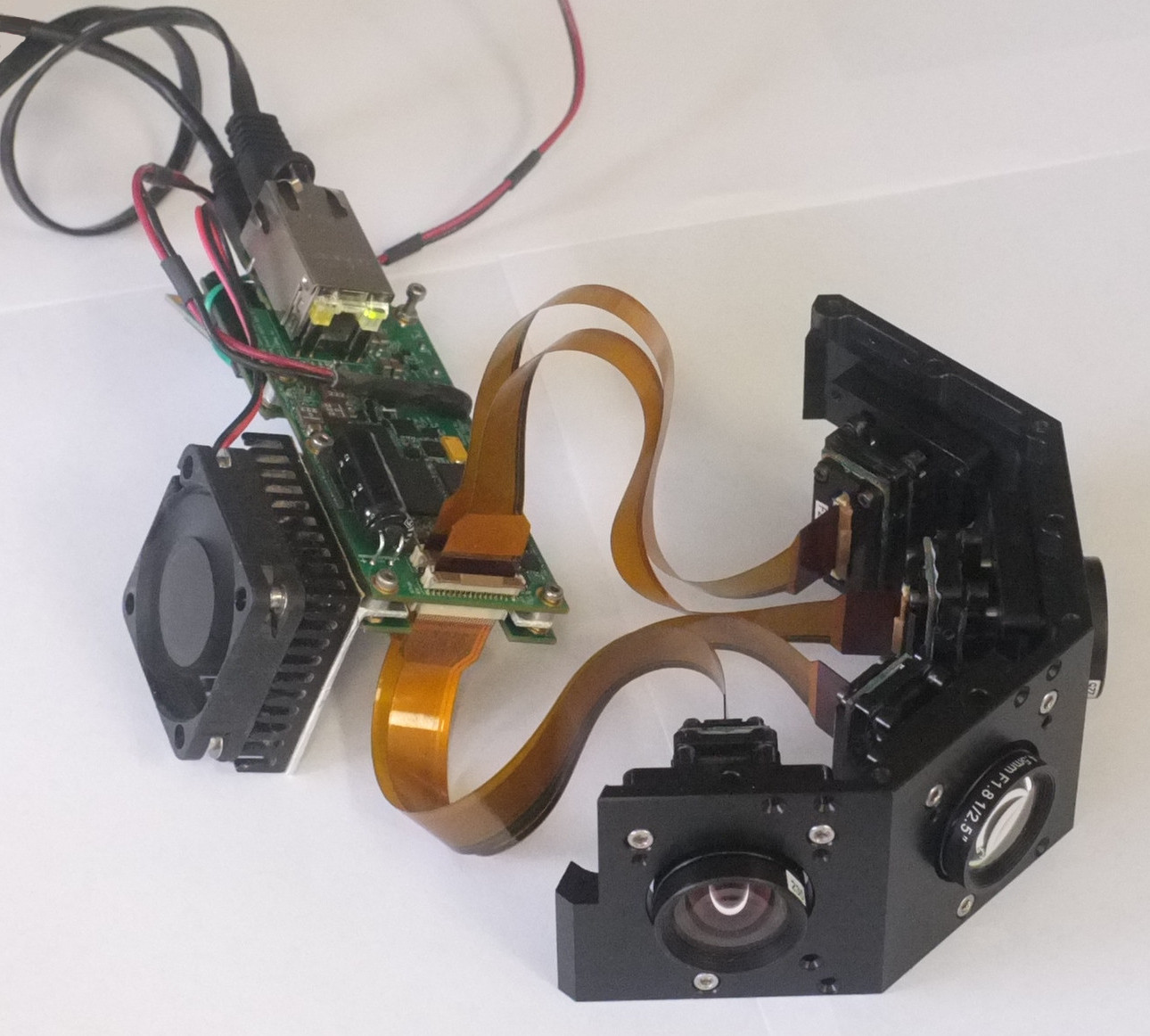
10393 with 4 image sensors
Finally all the parts of the NC393 prototype are tested and we now can make the
circuit diagram, parts list and PCB layout of this board public. About the half of the board components were tested immediately when the prototype was built –
it was almost two years ago – those tests did not require any FPGA code, just the initial software that was mostly already available from the distributions for the other boards based on the same Xilinx Zynq SoC. The only missing parts were the GPL-licensed
initial bootloader and
a few device drivers.
(more…)
July 29, 2015
by Andrey Filippov
Another update on the development of the NC393 camera: finished adding FPGA code that re-implements functionality of the NC353 camera (just with additional multi-sensor capability), including JPEG/JP4 compressors, IMU/GPS logger and inter-camera synchronization. Next step – simulation and debugging, and it will use co-simulating of the same sensor image data using the code of the existing NC353 camera. This involves updating of that camera code to the state compatible with the development tools we use, and so the additional sub-project was spawned.
(more…)
July 9, 2015
by Alexey
Widespread high-speed protocols, which are based on serial interfaces, have become easier and easier to implement on FPGAs. If you take a look at Xilinx’s chips series, you can monitor an evolution of embedded transceivers from some awkwardly inflexible models to much more compatible ones. Nowadays even the affordable 7 series FPGAs possess GTX transceivers. Basically, they represent a unification of various protocols phy-levels, where the versatility is provided by parameters and control input signals.
The problem is, for some reason GTX’s simulation model is a secured IP block. It means that without proprietary software it’s impossible to compile and simulate the transceiver. Moreover, we use Icarus Verilog for these purposes, which doesn’t provide deciphering capabilities for now, and doesn’t seem to ever be able to do so: http://sourceforge.net/p/iverilog/feature-requests/35/
Still, our NC393 camera has to use GTX as a part of SATA host controller design. That’s why it was decided to create a small simulation model, which shall behave as GTX, at least within some limitation and assumption. This was done so that we could create a full-fledged non-synthesizable verification environment and provide our customers with a universal within simulation purposes solution.
(more…)
« Previous Page —
Next Page »


