December 3, 2017
by Andrey Filippov and Oleg Dzhimiev
Multiple Subdomains for the Same Web Site
It is a common case when a company or organization uses multiple content management systems (CMS) and specialized web application to organize its web presence. We describe here how Elphel handles such CMS variety and provide the source code that can be customized for other similar sites.
(more…)
November 22, 2017
by Andrey Filippov
Elphel uses embedded GNU/Linux distribution based on Yocto. For most of our development (excluding just mechanical and PCB design) we use universal Eclipse IDE: for FPGA development, Linux kernel drivers development, embedded applications and web applications, for editing LaTeX texts. And we use this popular IDE for delivering pre-configured projects to our users to make it easier for them to start efficient modification of the initial camera software and then initiate the new projects.
(more…)
September 25, 2017
by Paulina Filippova and Fyodor Filippov
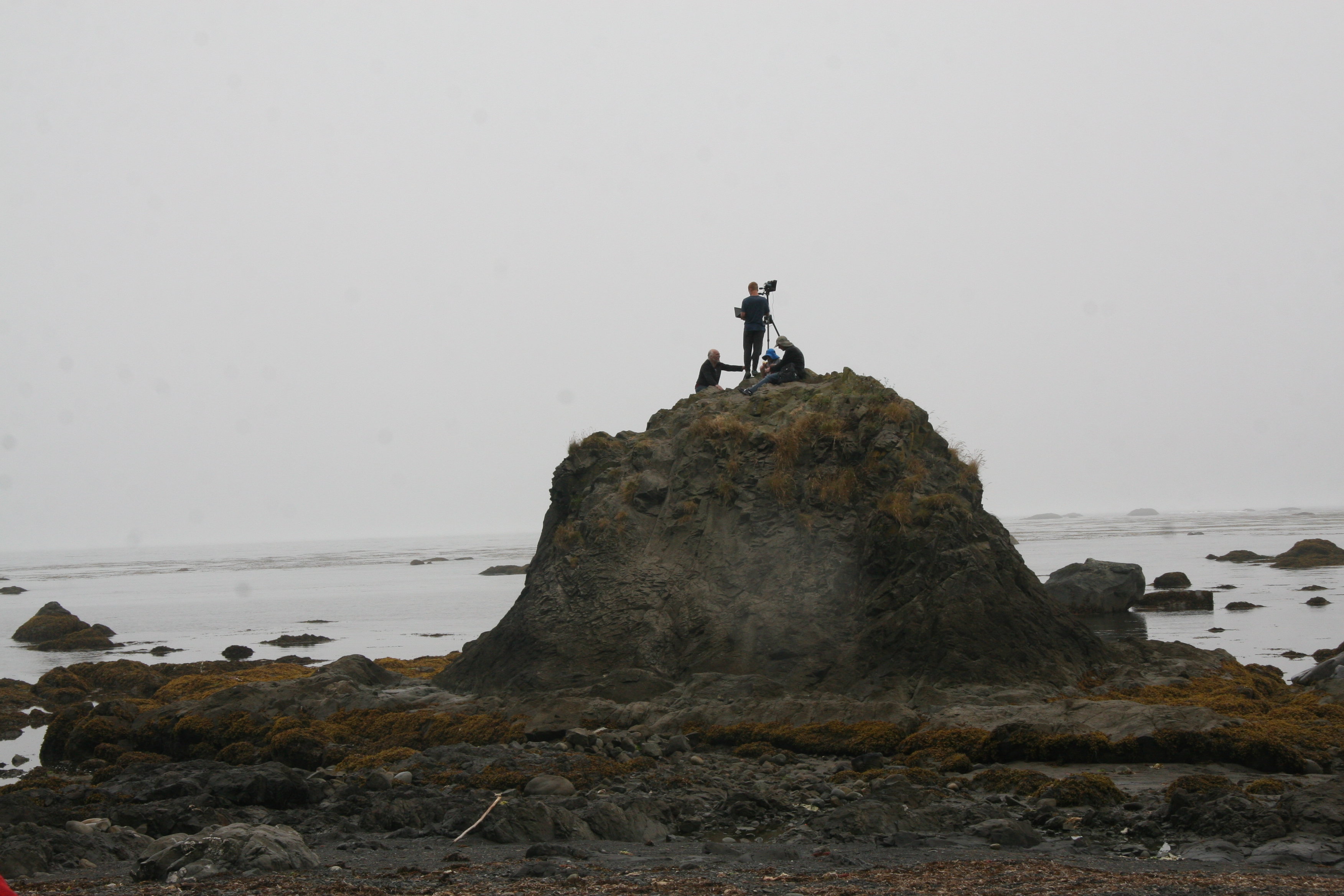
Setting 3D camera on the rock at Cape Alava
Testing 3D camera
on a road trip
In August of 2017, my family and I went on a trip to the Pacific Northwest, partially for a much needed vacation, but equally as importantly, to test my dad’s new 3D camera. My dad had been designing calibrated multi-sensor cameras for as long as I can remember, and since February was working determinately on developing principally new algorithms for reconstructing a 3D model from a set of 4 simultaneously taken photographs . Now that the camera and the software were ready, there was no better time to test it.
(more…)
September 20, 2017
by Andrey Filippov
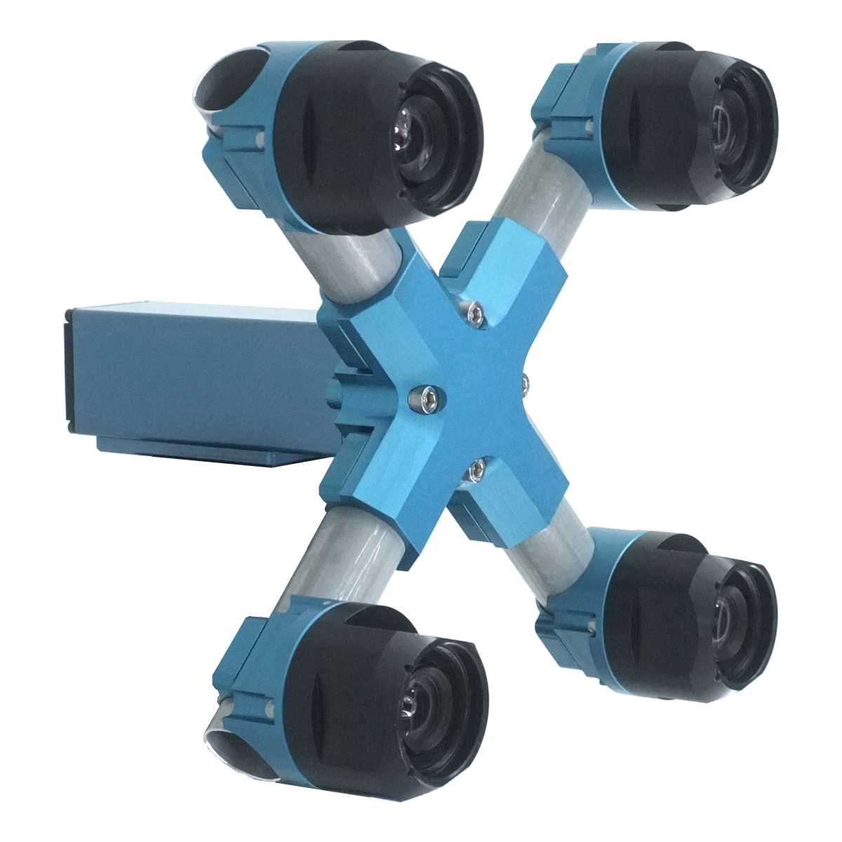
Figure 1. Four sensor stereo camera
Scroll down or just hyper-jump to Scene viewer for the links to see example images and reconstructed scenes.
(more…)
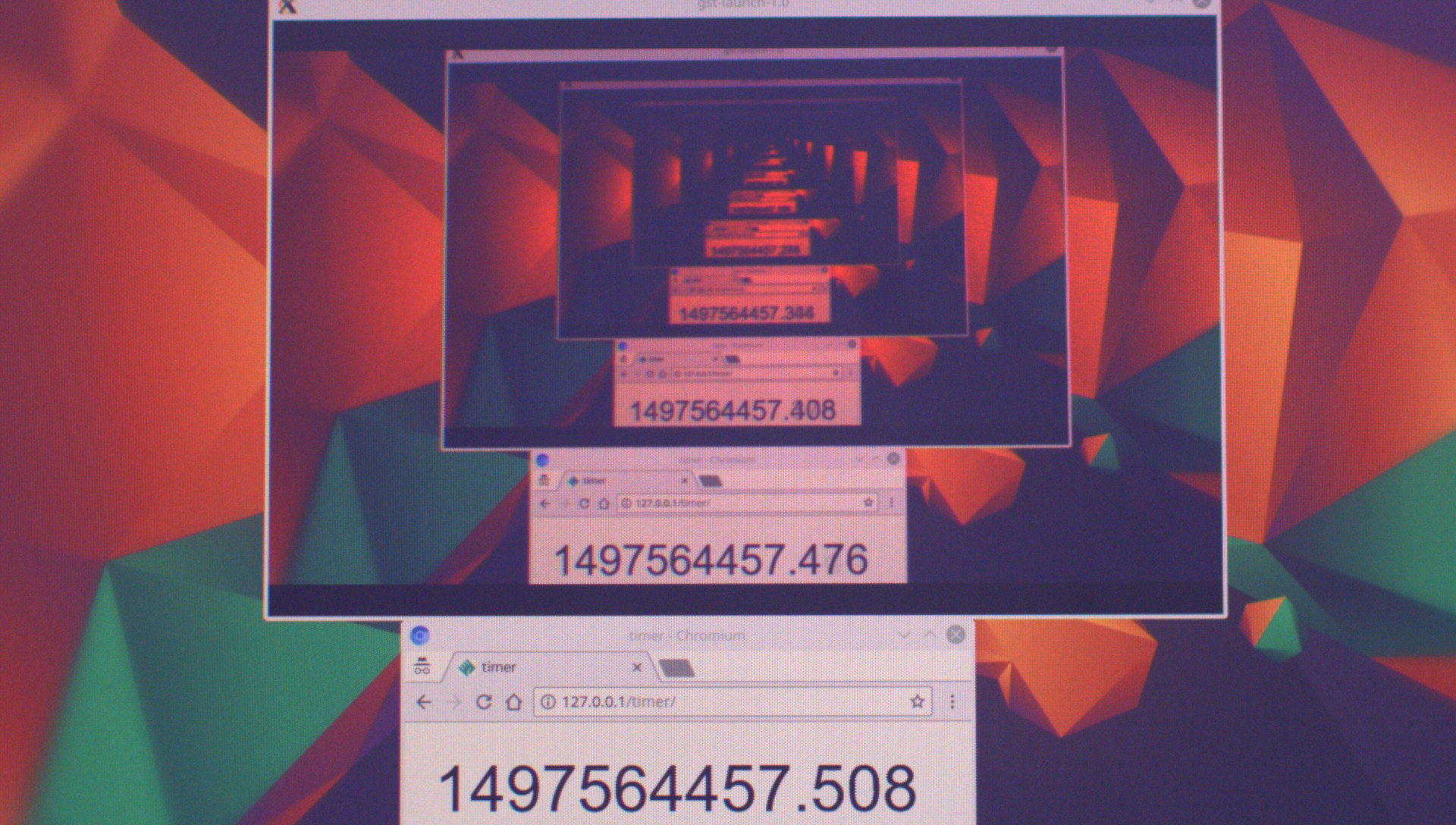
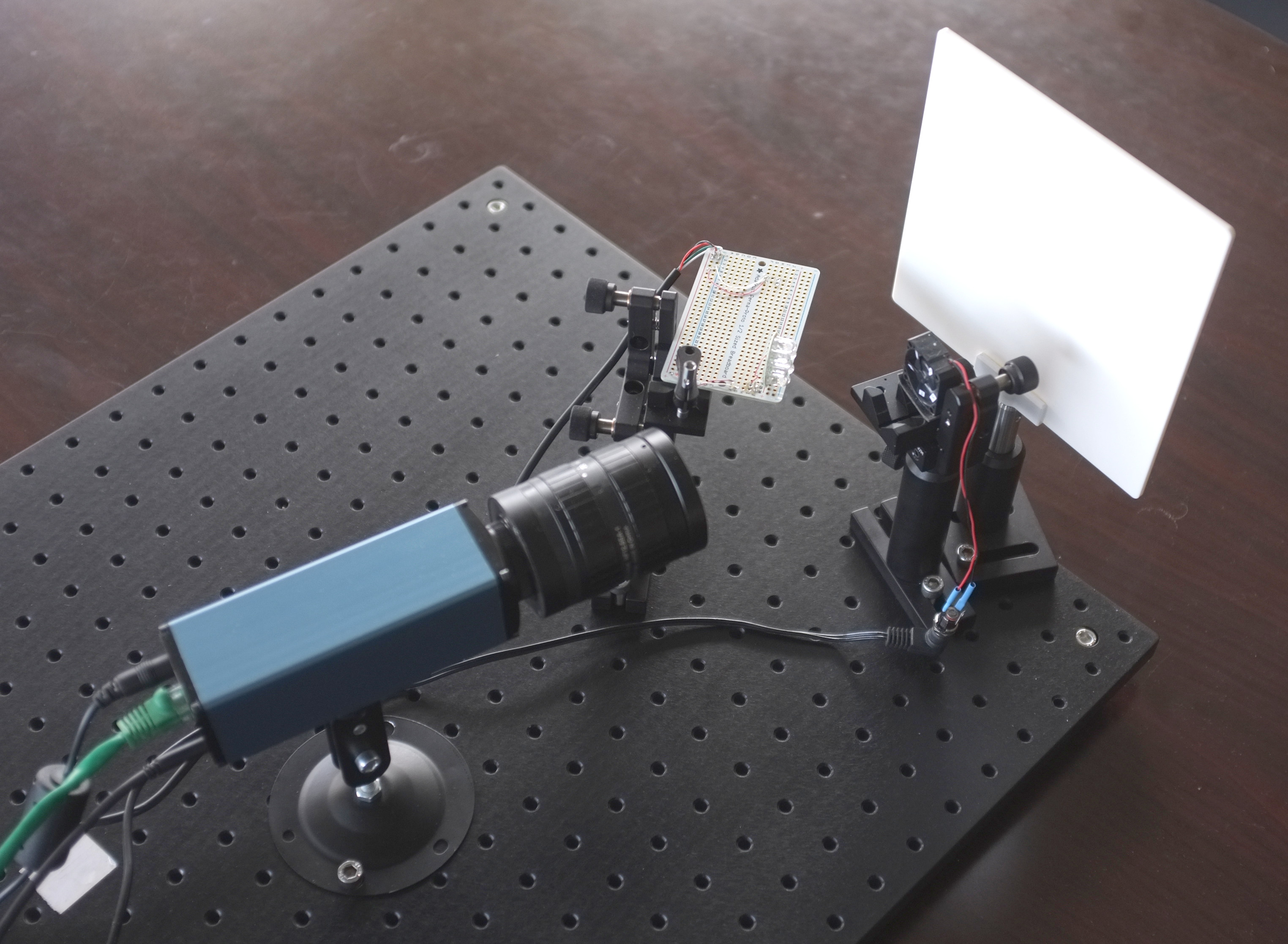
July 11, 2017
by Oleg Dzhimiev

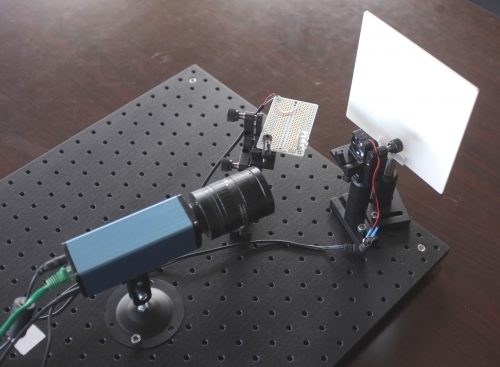
Fig.1 Live stream latency testing
Recently we had an inquiry whether our cameras are capable of streaming low latency video. The short answer is yes, the camera’s average output latency for 1080p at 30 fps is ~16 ms. It is possible to reduce it to almost 0.5 ms with a few changes to the driver.
However the total latency of the system, from capturing to displaying, includes delays caused by network, pc, software and display.
In the results of the experiment (similar to this one) these delays contribute the most (around 40-50 ms) to the stream latency – at least, for the given equipment.
(more…)
January 19, 2017
by Andrey Filippov
Fig.1. Image comparison of the different processing stages output
Results of the processing of the color image
Previous blog post “Lens aberration correction with the lapped MDCT” described our experiments with the lapped MDCT[1] for optical aberration corrections of a single color channel and separation of the asymmetrical kernel into a small asymmetrical part for direct convolution and a larger symmetrical one to be applied in the frequency domain of the MDCT. We supplemented this processing chain with additional steps of the image conditioning to evaluate the overall quality of the of the results and feasibility of the MDCT approach for processing in the camera FPGA.
Image comparator in Fig.1 allows to see the difference between the images generated from the results of the several stages of the processing. It makes possible to compare any two of the image layers by either sliding the image separator or by just clicking on the image – that alternates right/left images. Zoom is controlled by the scroll wheel (click on the zoom indicator fits image), pan – by dragging.
Original image was acquired with Elphel model 393 camera with 5 Mpix MT9P006 image sensor and Sunex DSL227 fisheye lens, saved in jp4 format as a raw Bayer data at 98% compression quality. Calibration was performed with the Java program using calibration pattern visible in the image itself. The program is designed to work with the low-distortion lenses so fisheye was a stretch and the calibration kernels near the edges are just replicated from the ones closer to the center, so aberration correction is only partial in those areas.
First two layers differ just by added annotations, they both show output of a simple bilinear demosaic processing, same as generated by the camera when running in JPEG mode. Next layers show different stages of the processing, details are provided later in this blog post.
(more…)
January 7, 2017
by Andrey Filippov
Modern small-pixel image sensors exceed resolution of the lenses, so it is the optics of the camera, not the raw sensor “megapixels” that define how sharp are the images, especially in the off-center areas. Multi-sensor camera systems that depend on the tiled images do not have any center areas, so overall system resolution may be as low as that of is its worst part.
Fig. 1. Lateral chromatic aberration and Bayer mosaic: a) monochrome (green) PSF, b) composite color PSF, c) Bayer mosaic of the sensor, d) distorted mosaic for the chromatic aberration of b).
De-mosaic processing and chromatic aberrations
Our current cameras role is to preserve the raw sensor data while providing some moderate compression, all the image correction is applied during post-processing. Handling the lens aberration has to be done before color conversion (or de-mosaicing). When converting Bayer data to color images most cameras start with the calculation of the “missing” colors in the RG/GB pattern using 3×3 or 5×5 kernels, this procedure relies on the specific arrangement of the color filters.
Each of the red and blue pixels has 4 green ones at the same distance (pixel pitch) and 4 of the opposite (R for B and B for R) color at the equidistant diagonal locations. Fig.1. shows how lateral chromatic aberration disturbs these relations.
Fig.1a is the point-spread function (PSF) of the green channel of the sensor. The resolution of the PSF measurement is twice higher than the pixel pitch, so the lens is not that bad – horizontal distance between the 2 greens in Fig.1c corresponds to 4 pixels of Fig.1a. It is also clearly visible that the PSF is elongated and the radial resolution in this part of the image is better than the tangential one (lens center is left-down).
Fig.1b shows superposition of the 3 color channels: blue center is shifted up-and-right by approximately 2 PSF pixels (so one actual pixel period of the sensor) and the red one – half-pixel left-and-down from the green center. So the point light of a star, centered around some green pixel will not just spread uniformly to the two “R”s and two “B”s shown connected with lines in Fig.1c, but the other ones and in different order. Fig.1d illustrates the effective positions of the sensor pixels that match the lens aberration.
(more…)
December 22, 2016
by Mikhail Karpenko
Sometimes we need to test disks connected to camera and find out if a particular model is a good candidate for in-camera stream recording application. Such disks should not only be fast enough in terms of write speed, but they should have short ‘response time’ to write commands. This ‘response time’ is basically the time between command sent to disk and a response from disk that this command has finished. The time between the two events is related to total write speed, but it can vary due to processes going on in internal disk controller.
The fluctuations in disk response time can be an important parameter for high bandwidth streaming applications in embedded systems as this value allows to estimate the data buffer size needed during recording, but this may be not very critical parameter for typical PC applications as modern computers are equipped with large amount of RAM. We have not found any suitable parameter in disk specifications we had which would give us a hint for the buffer size estimation and developed a small test program for this purpose.
(more…)
December 17, 2016
by Andrey Filippov
As we finished with the basic camera functionality and tested the first Eyesis4π built with the new 10393 system boards (it is smaller, requires less power and, is faster) we are moving forward with the in-camera image processing. We plan to combine our current camera calibration methods that require off-line post processing and the real-time image correction using the camera own FPGA resources. This project development will require switching between the actual FPGA coding and the software implementation of the same algorithms before going to the next step – software is still easier to design. The first part was in FPGA realm – it was to implement the fundamental image processing block that we already know we’ll be using and see how much of the resources it needs.
DCT type IV as a building block for in-camera image processing
We consider a small (8×8 pixel) DCT-IV to be a universal block for conditioning of the raw acquired images. Such operations as lens optical aberrations correction, color conversion (de-mosaic) in the presence of the lateral chromatic aberration, image rectification (de-warping) are easier to perform in the frequency domain using convolution-multiplication property and other algorithms.
In post-processing we use DFT (Discrete Fourier Transform) over rather large (64×64 to 512×512) tiles, but that would be too much for the in-camera processing. First is the tile size – for good lenses we do not need that large convolution kernels. Additionally we plan to combine several processing steps into one (based on our off-line post-processing experience) and so we do not need to sub-sample images – in our current software we double resolution of the raw images at the beginning and scale back the final result to reduce image degradation caused by re-sampling.
The second area where we plan to reduce computations is the replacement of the DFT with the DCT that is designed to be fed with the pure real data and so requires less arithmetic operations than DFT that processes complex input values.
Why “type IV” of the DCT?
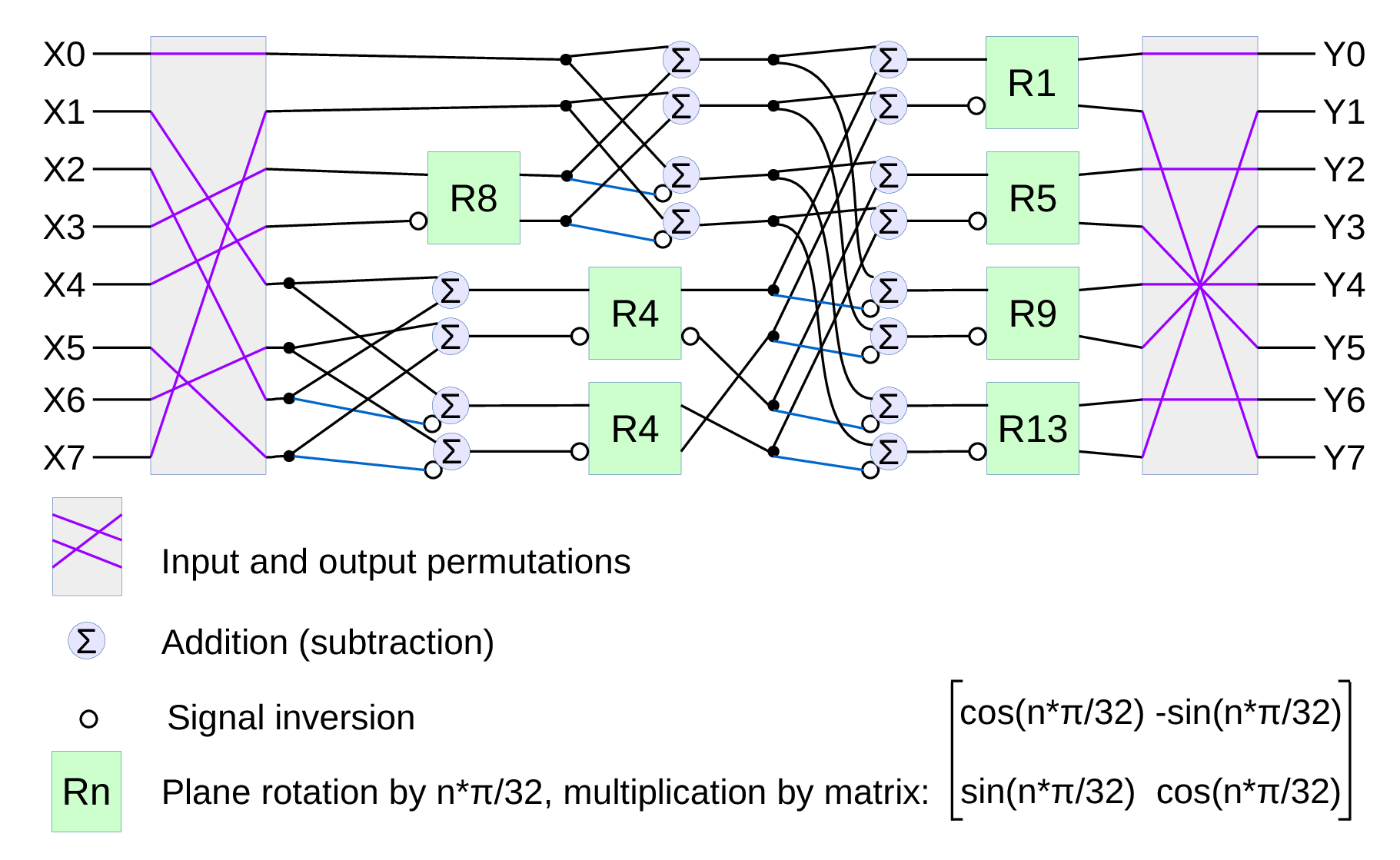
Fig.1. Signal flow graph for DCT-IV
We already have DCT type II implemented for the JPEG/JP4 compression, and we still needed another one. Type IV is used in audio compression because it can be converted to a modified discrete cosine transform (MDCT) – a procedure when multiple overlapped windows are processed one at a time and the results are seamlessly combined without any block artifacts that are familiar for the JPEG with low settings of the compression quality. We too need lapped transform to process large images with relatively small (much smaller than the image itself) convolution kernels, and DCT-IV is a perfect fit. 8-point DCT-IV allows to implement transformation of 16-point segments with 8-point overlap in a reversible manner – the inverse transformation of 8-point data may be converted to 16-point overlapping segments, and being added together these segments result in the original data.
(more…)
October 24, 2016
by Oleg Dzhimiev
Operation modes in conventional CMOS image sensors with the electronic rolling shutter
Flash test setup
Most of the CMOS image sensors have Electronic Rolling Shutter – the images are acquired by scanning line by line. Their strengths and weaknesses are well known and extremely wide usage made the technology somewhat perfect – Andrey might have already said this somewhere before.
There are CMOS sensors with a Global Shutter BUT (if we take the same optical formats):
- because of more elements per pixel – they have lower full well capacity and quantum efficiency
- because analog memory is used – they have higher dark current and higher shutter ratio
Some links:
So, the typical sensor with ERS may support 3 modes of operation:
- Electronic Rolling Shutter (ERS) Continuous
- Electronic Rolling Shutter (ERS) Snapshot
- Global Reset Release (GRR) Snapshot
GRR Snapshot was available in the 10353 cameras but ourselves we never tried it – one should have write directly to the sensor’s register to turn it on. But now it is tested and working in 10393s available through the TRIG (0x14) parameter.
(more…)
« Previous Page —
Next Page »