by Oleg Dzhimiev
1. [Done] Add headers and commit to CVS.
2. [Done] Optimize BRAM usage.
4 BRAMs & 8 MULTs, ~150MHz after Synthesis (will be less of course after implementation)
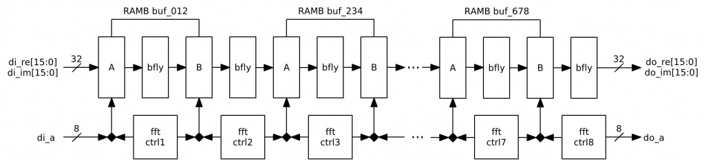
Fig.1 FFT256 diagram
3. [In Progress] FFT256 Verification.
NOTES:
- Do wires to BRAM36X36 and to MULT18X18 are shared? Can I use all 28 BRAMs and 28 MULTs in one design?
TODO:
- Check if the FFT256 results are correct.
- Write a correlation computation block.
- Write complex multiplication of 2 FFT256s (in order to get a cross-correlation spectrum)
- Add IFFT256 run for the multiplication result.
by Andrey Filippov
Senor interface on teh 10373 board – upgrade to high speed serial?
by Oleg Dzhimiev
1. [Done] Add 1/256 after the last stage and check the simulation.
- Added a 1-bit right shift (1/2) after each “butterfly” – in the end it is 1/256 accumulated. This can be an early rounding. With 12 bits of color after all the sums in 8 stages the final value can be up to 20 bits wide. Only 16 bits are stored so the 1-bit right shift keeps the value within 12. Alternatively, a 4-bit right shift can be applied after every 4 stages.
2. [Done] Make a simple simulation with FFT256 and IFFT256.
- Made a testbench FFT256-IFFT256. The input and the output differ. Need to check more properly overflows in calculations and cosine tables.
- Corrected a mistake concerning two’s complement 8 bits expanding to 18 (just filling the upper part with the 7th bit(Hi)). Same for 16 bit values before 18×18 multiplication.
3. [In Progress] Optimize BRAM usage, the goal is 5 or 6 BRAMs & 8 MULTs (not sure for the input and output buffer)
- The plan is to use 4 BRAM32X32s and the output will be not buffered – the “butterfly” output needs to be delayed by 2 tacts then. And a specific writes and write order to input buffer will be needed.
TODO:
- Optimize BRAM usage.
- Add headers and commit to CVS.
- Write a correlation computation block.
- Set up memory controller for frames read/write.
- Integrate the correlation block to 10359’s firmware.
by Oleg Dzhimiev
1. Wrote a short manual on how to connect 10359 with 10353 and sensors: link
2. Almost finished coding FFT256 main module with no integration to 10359 code.
FFT is performed in 8 conveyor organized stages. Each stage is similar to as described here. So far each stage uses 1 BRAM and the 1 MULT18X18 (for the “butterfly”) + 1 BRAM for the input buffer – 9 BRAMs + 8 MULT18X18s. Plus other logic – 1 FFT256 uses 16% of FPGA resourses.
But, each ‘stage’ uses only a half of the BRAM (256 real and 256 imaginary). So it’s possible to optimize the module, the ways are:
- Currently the “butterfly” writes out Re & Im parts simultaneously using both (A and B) BRAM ports and only lower 512 cells. It is possible to use only one BRAM port doing writing and reading ‘Re’s and ‘Im’s sequentially and using lower 512 cells (as Re parts are calculated earlier) while another port can be used for other stage and access higher 512 cells.
- There are pauses between accesses to a BRAM – so stage-modules can be made working in turns.
Load time + Computation time + Readout time @10ns Clk ~ 2.5us + 8x5us + 2.5us = 45us.
But here it takes them 15us@25MHz to compute FFT256. They probably use only 1 tact for the “butterfly”. As I use only one MULT18X18 it takes 4 tacts to get the result:
4 x 128 x 10 ns ~ 5.12us per “butterfly”. With 1 tact & 4 MULTs it could be 1.28us and the overall FFT256 time 15us. But their clock is 4 times slower. How did they do that? Is it possibe to make a 4us FFT256 @96MHz?
With the 8-stage conveyor structure it speeds up by 8 times against non-conveyored computation. For a full resolution frame 2592×1944 with 128 bit overlap in a line it will take ~ (45us x (2592/128) x 1944) / 8 ~ 50us x 20 x 2000 / 8 = 0.25s or 4 fps
- Add 1/N after the last stage and check the simulation.
- Make a simple simulation with FFT256 and IFFT256.
- Optimize BRAM usage, the goal is 5 or 6 BRAMs & 8 MULTs (not sure for the input and output buffer)
- Can I get out of the 16-bit value border? Not cool if yes.
by Andrey Filippov
This is a combination of two features I just added together as I had to get into the data pipeline in the FPGA.
First is correction of lens and sensor vignetting – http://en.wikipedia.org/wiki/Vignetting (Micron sensor have some of this capabilities on-chip, but not really nice and not portable to other sensors). This can be especially important for wide angle lenses and fish eyes. It is better to do this correction in-camera even if higher order compensation (not just quadratic) may be done in post-processing. In-camera has advantage of doing it before gamma-tables that compresses 12-bit data to just 8, so it is possible to save somewhat on S/N ratio and increase the overall dynamic range.
In addition to the vignetting of the lens that is usually rather symmetrical around the axis, sensor may add asymmetry related to the microlenses. Kodak KAI11002 used in book scanning have very different sensitivity vs. angle functions in vertical and horizontal directions.
So I implemented separate coefficients for X and Y (and am proud of remembering how to calculate such functions without a single multiplication 🙂 ) This functions is common for all color channels (it will not be difficult to make it individual if needed). The F(x,y) is 17-bit (limited by the on-chip-multiplier used to apply the F(x,y) to the pixel data), so if I set x1.0 (in the center) 15 bits up to x4 correction can be applied.
Second feature is just per-color scaling before the gamma tables is just to reduce CPU load and provide more flexibility. Currently the color scaling is performed it 2 ways – re-calculating gamma tables and sensor analog gain. Analog gain is not very precise and have large steps so it is not enough for color balancing. Scaling gamma tables works good when the tables are really gamma (not arbitrary ones) where scaling of input can be replaced by scaling of the output. With the new feature it is possible to scale the before-gamma table without re-calculating/reloading the gamma tables to the FPGA. These (4 of them) coefficients are also 17 bit, and there is an additional scaler (shifter) after, so if you do not need 4:1
range but 2:1 is enough you can increase the precision by assigning x1.0 to 0x10000 instead of the 0x8000 (16 bits vs 15 bits).
I’m testing it and will include control into the drivers. It will be rather easy to make a auto-correction by integrating pixel data (raw data inside the camera is available as a file but it is better to handle it in C rather than PHP) in say 16 zones (4×4) and then calculating the required parameters. In some cases it can be used to compensate for a uneven illumination (in the center), not just the lens/sensor.

Black area is still a bug, not a feature. It should stay at maximum gain, not zero.
by admin
This newly formed Blog will be THE homebase for brand new developed features and most recent additions and changes in the Elphel source code and hardware design.
The name “development” and not “developer” was chosen on purpose as this portal is not just intended for those already working with the camera and software.
You can subscribe to the newsletter in the right sidebar if you want to automatically be informed about ongoing camera development.
