by Andrey Filippov
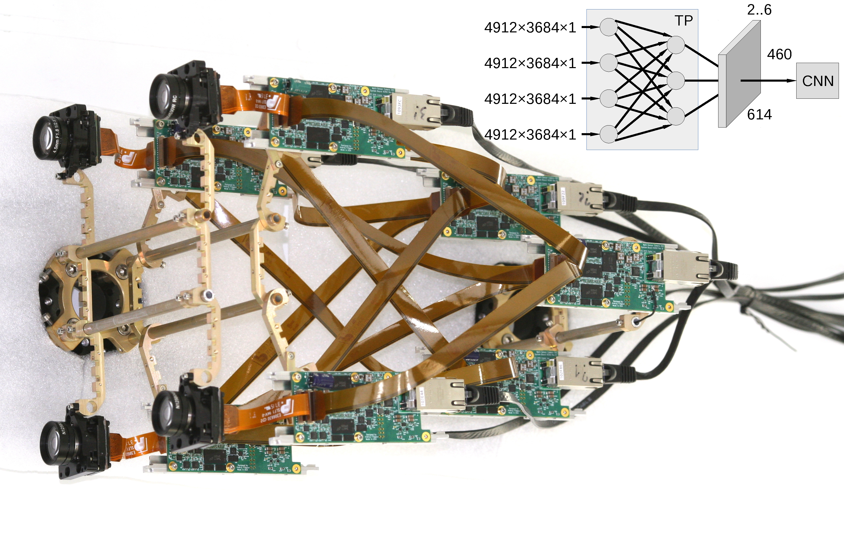
Figure 1. Multi-board setup for the TP+CNN prototype
Featured on Image Sensors World
This article describes our next steps that will continue the year-long research on high resolution multi-view stereo for long distance ranging and 3-D reconstruction. We plan to fuse the methods of high resolution images calibration and processing, already emulated functionality of the Tile Processor (TP), RTL code developed for its implementation and the Convolutional Neural Network (CNN). Compared to the CNN alone this approach promises over a hundred times reduction in the number of input features without sacrificing universality of the end-to-end processing. The TP part of the system is responsible for the high resolution aspects of the image acquisition (such as optical aberrations correction and image rectification), preserves deep sub-pixel super-resolution using efficient implementation of the 2-D linear transforms. Tile processor is free of any training, only a few hyperparameters define its operation, all the application-specific processing and “decision making” is delegated to the CNN.
(more…)
by Andrey Filippov
This post continues discussion of the small tile space-variant frequency domain (FD) image processing in the camera, it demonstrates that modulated complex lapped transform (MCLT) of the Bayer mosaic color images requires almost 3 times less computational resources than that of the full RGB color data.
“Small Tile” and “Space Variant”
Why “small tile“? Most camera images have short (up to few pixels) correlation/mutual information span related to the acquisition system properties – optical aberrations cause a single scene object point influence a small area of the sensor pixels. When matching multiple images increase of the window size reduces the lateral (x,y) resolution, so many of the 3d reconstruction algorithms do not use any windows at all, and process every pixel individually. Other limitation on the window size comes from the fact that FD conversions (Fourier and similar) in Cartesian coordinates are shift-invariant, but are sensitive to scale and rotation mismatch. So targeting say 0.1 pixel disparity accuracy the scale mismatch should not cause error accumulation over window width exceeding that value. With 8×8 tiles (16×16 overlapped) acceptable scale mismatch (such as focal length variations) should be under 1%. That tolerance is reasonable, but it can not get much tighter.
What is “space variant“? One of the most universal operations performed in the FD is convolution (also related to correlation) that exploits convolution-multiplication property. Mathematically convolution applies the same operation to each of the points of the source data, so shifted object of the source image produces just a shifted result after convolution. In the physical world it is a close approximation, but not an exact one. Stars imaged by a telescope may have sharper images in the center, but more blurred in the peripheral areas. While close (angularly) stars produce almost the same shape images, the far ones do not. This does not invalidate convolution approach completely, but requires kernel to (smoothly) vary over the input images [1, 2], makes it a space-variant kernel.
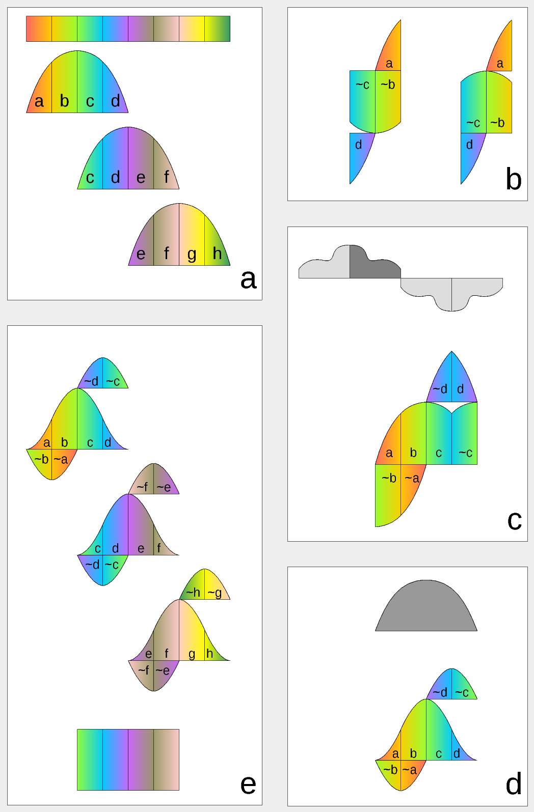
Figure 1. Complex Lapped Transform with DCT-IV/DST-IV: time-domain aliasing cancellation (TDAC) property. a) selection of overlapping input subsequences 2*N-long, multiplication by sine window; b) creating N-long sequences for DCT-IV (left) and DST-IV (right); c) (after frequency domain processing) extending N-long sequence using DCT-IV boundary conditions (DST-IV processing is similar); d) second multiplication by sine window; e) combining partial data
There is another issue related to the space-variant kernels. Fractional pixel shifts are required for multiple steps of the processing: aberration correction (obvious in the case of the lateral chromatic aberration), image rectification before matching that accounts for lens optical distortion, camera orientation mismatch and epipolar geometry transformations. Traditionally it is handled by the image rectification that involves re-sampling of the pixel values for a new grid using some type of the interpolation. This process distorts the signal data and introduces non-linear errors that reduce accuracy of the correlation, that is important for subpixel disparity measurements. Our approach completely eliminates resampling and combines integer pixel shift in the pixel domain and delegates the residual fractional pixel shift (±0.5 pix) to the FD, where it is implemented as a cosine/sine phase rotator. Multiple sources of the required pixel shift are combined for each tile, and then a single phase rotation is performed as a last step of pixel domain to FD conversion.
Frequency Domain Conversion with the Modulated Complex Lapped Transform
Modulated Complex Lapped Transform (MCLT)[3] can be used to split input sequence into overlapping fractions, processed separately and then recombined without block artifacts. Popular application is the signal compression where “processed separately” means compressed by the encoder (may be lossy) and then reconstructed by the decoder. MCLT is similar to the MDCT that is implemented with DCT-IV, but it additionally preserves and allows frequency domain modification of the signal phase. This feature is required for our application (fractional pixel shifts and asymmetrical lens aberrations modify phase), and MCLT includes both MDCT and MDST (that use DCT-IV and DST-IV respectively). For the image processing (2d conversion) four sub-transforms are needed:
- horizontal DCT-IV followed by vertical DCT-IV
- horizontal DST-IV followed by vertical DCT-IV
- horizontal DCT-IV followed by vertical DST-IV
- horizontal DST-IV followed by vertical DST-IV
(more…)
by Paulina Filippova and Fyodor Filippov
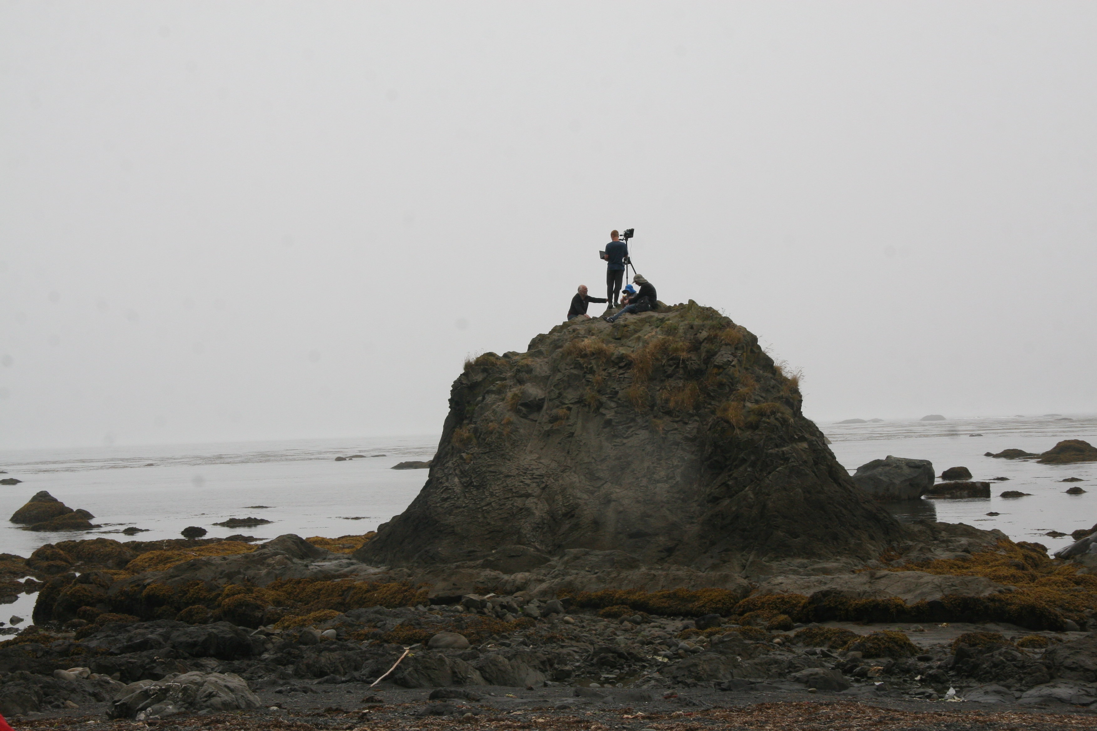
Setting 3D camera on the rock at Cape Alava
Testing 3D camera
on a road trip
In August of 2017, my family and I went on a trip to the Pacific Northwest, partially for a much needed vacation, but equally as importantly, to test my dad’s new 3D camera. My dad had been designing calibrated multi-sensor cameras for as long as I can remember, and since February was working determinately on developing principally
new algorithms for reconstructing a 3D model from a set of 4 simultaneously taken photographs . Now that the camera and the software were ready, there was no better time to test it.
(more…)
by Andrey Filippov
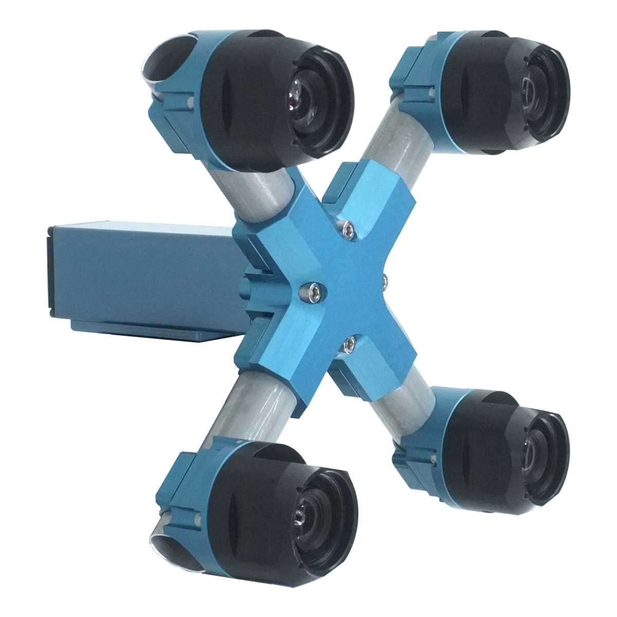
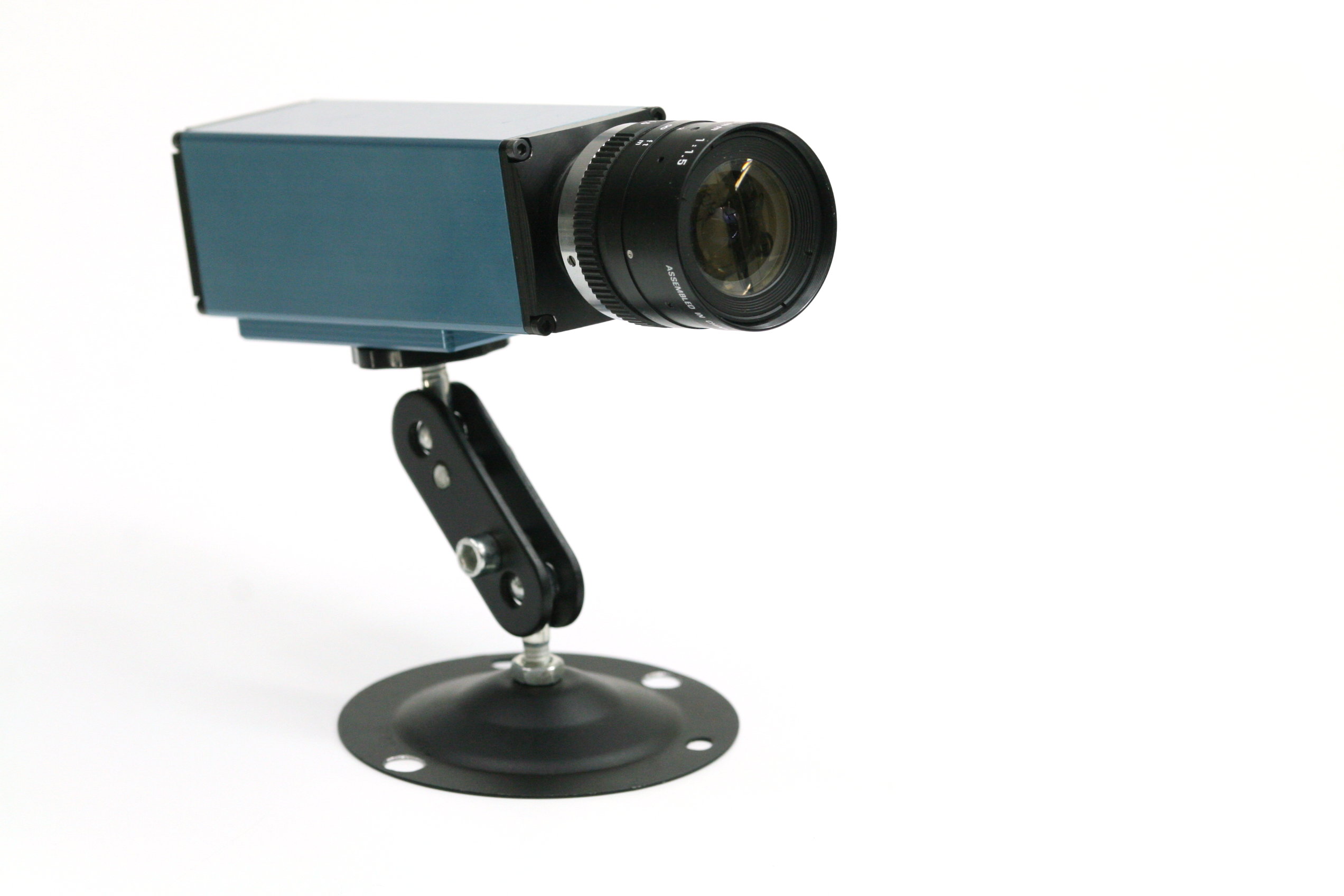
Figure 1. Four sensor stereo camera
by Andrey Filippov
Fig.1. Image comparison of the different processing stages output
Results of the processing of the color image
Previous blog post
“Lens aberration correction with the lapped MDCT” described our experiments with the lapped MDCT
[1] for optical aberration corrections of a single color channel and separation of the asymmetrical kernel into a small asymmetrical part for direct convolution and a larger symmetrical one to be applied in the frequency domain of the MDCT. We supplemented this processing chain with additional steps of the image conditioning to evaluate the overall quality of the of the results and feasibility of the MDCT approach for processing in the camera FPGA.
Image comparator in Fig.1 allows to see the difference between the images generated from the results of the several stages of the processing. It makes possible to compare any two of the image layers by either sliding the image separator or by just clicking on the image – that alternates right/left images. Zoom is controlled by the scroll wheel (click on the zoom indicator fits image), pan – by dragging.
Original image was acquired with Elphel model 393 camera with 5 Mpix MT9P006 image sensor and Sunex DSL227 fisheye lens, saved in
jp4 format as a raw Bayer data at 98% compression quality. Calibration was performed with the Java
program using calibration pattern visible in the image itself. The program is designed to work with the low-distortion lenses so fisheye was a stretch and the calibration kernels near the edges are just replicated from the ones closer to the center, so aberration correction is only partial in those areas.
First two layers differ just by added annotations, they both show output of a simple bilinear demosaic processing, same as generated by the camera when running in JPEG mode. Next layers show different stages of the processing, details are provided later in this blog post.
(more…)
by Andrey Filippov
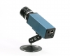
Two weeks ago we were making photos of our first production NC393 camera to post an announcement of the new product availability. We got all the mechanical parts and most of the electronic boards (14MPix version will be available shortly) and put them together. Nice looking camera, powered by a high performance SoC (dual ARM plus FPGA), packaged in a lightweight aluminum extrusion body, providing different options for various environments – indoors, outdoors, on board of the UAV or even in the open space with no air (cooling is important when you run most of the FPGA resources at full speed).
Tons of potential possibilities, but the finished camera did not seem too exciting – there are so many similar looking devices available.

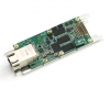
NC393 camera, back panel view. Includes DC power input (12-36V and 20-75V options), GigE, microSD card (bootable), microUSB(type B) connector for a system console with reset and boot source selection, USB/eSATA combo connector, microUSB(type A) and 2.5mm 4-contact barrel connector for external synchronization I/O
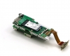
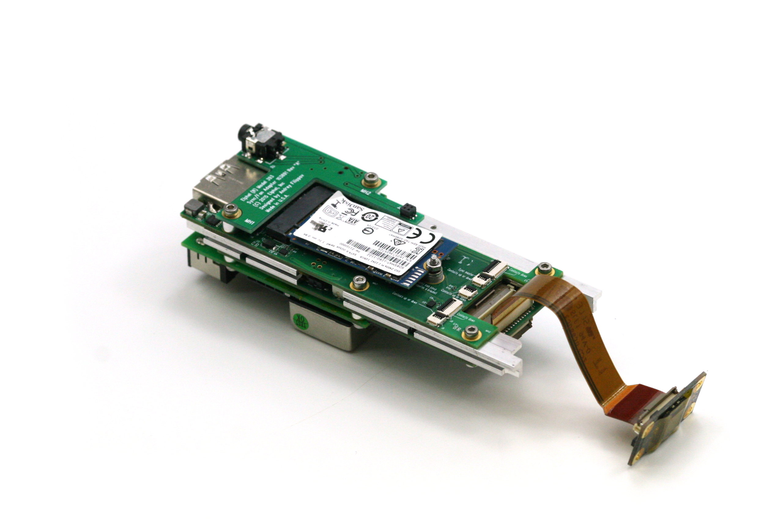
NC393 assembled boards: 10393(system board), 10385 (power supply board), 10389(interface board), 10338e (sensor board) and 103891 - synchronization adapter board, view from 10389. m.2 2242 SSD shown, bracket for the 2260 format provided. 10389 internal connectors include inter-camera synchronization and two of 3.3VDC+5.0VDC+I2C+USB ones.
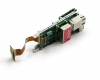
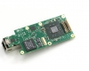
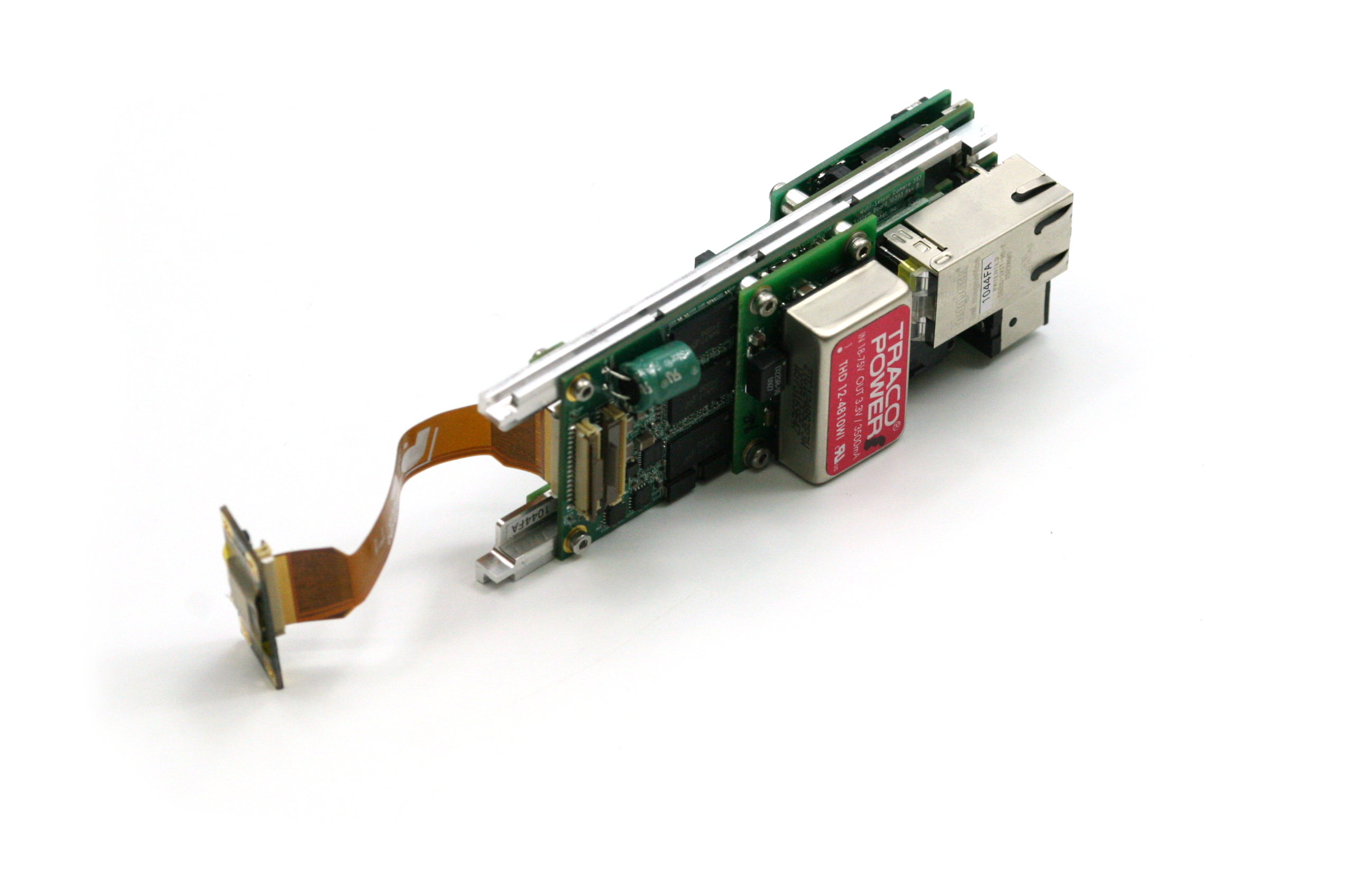
NC393 assembled boards: 10393(system board), 10385 (power supply board), 10389(interface board), 10338e (sensor board) and 103891 - synchronization adapter board, view from 10385
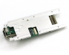
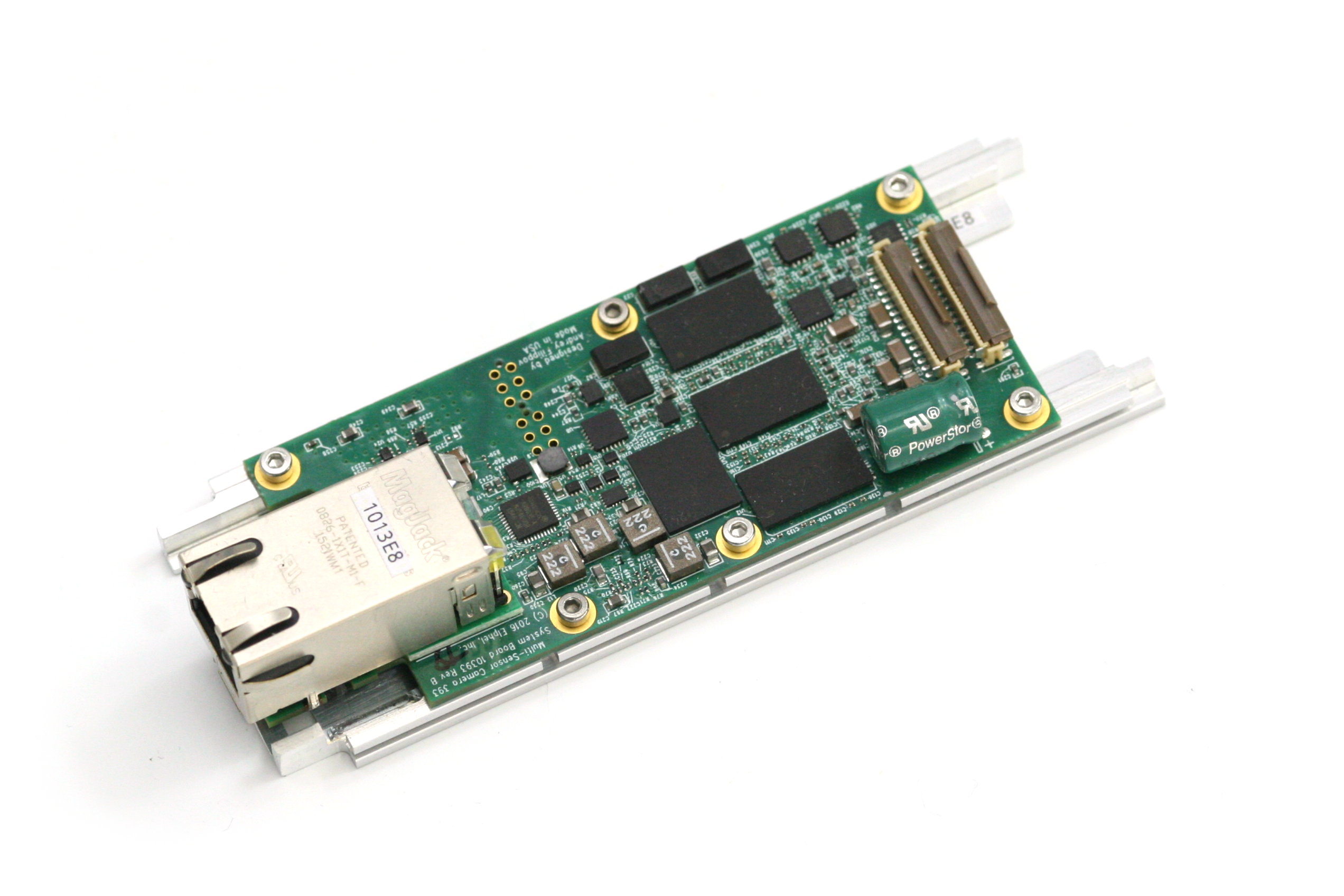
10393 system board attached to the heat frame, view from the heat frame. There is a large aluminum heat spreader attached to the other side of the frame with thermal conductive epoxy that provides heat transfer from the CPU without the use of any spring load. Other heat dissipating components use heat pads.
10393 system board attached to the heat frame, view from the 10393 board
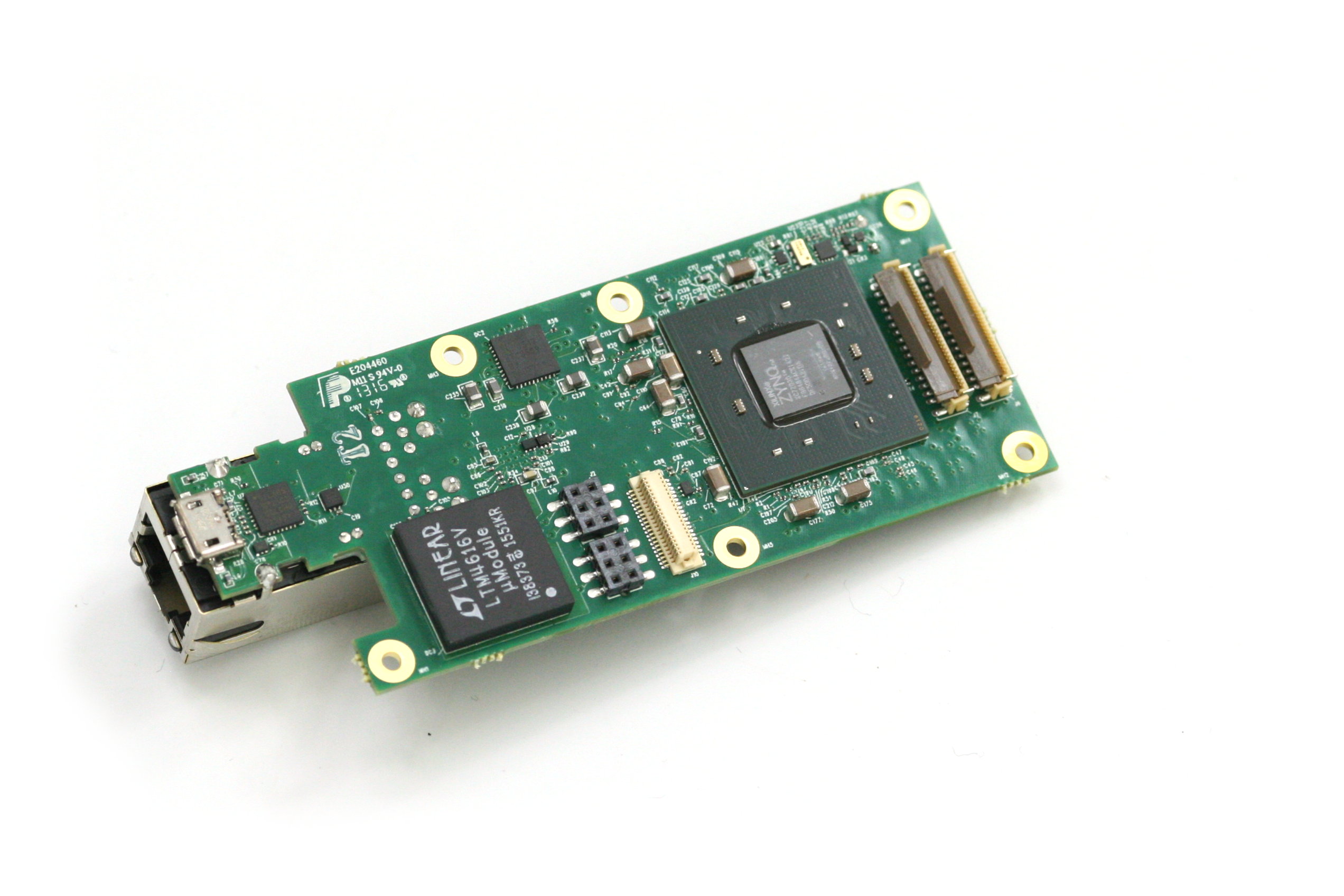
10393 system board, view from the processor side
An obvious reason for our dissatisfaction is that the single-sensor camera uses just one of four available sensor ports. Of course it is possible to use more of the freed FPGA resources for a single image processing, but it is not what you can use out of the box.
Many of our users buy camera components and arrange them in their custom setup themselves – that does not have a single-sensor limitation and it matches our goals – make it easy to develop a custom system, or
sculpture the camera to meet your ideas as stated on our web site. We would like to open the cameras to those who do not have capabilities of advanced mechanical design and manufacturing or just want to try new camera ideas immediately after receiving the product.
(more…)
by Andrey Filippov
“Temporary diversion” that lasted for three years

Last years we were working on the multi-sensor cameras and optical parts of the cameras. It all started as a
temporary diversion from the development of the model 373 cameras that we planned to use instead of our current model 353 cameras based on the discontinued Axis CPU. The problem with the 373 design was that while the prototype was assembled and successfully tested (together with two new add-on boards) I did not like the bandwidth between the FPGA and the CPU – even as I used as many connection channels between them as possible. So while the Texas Instruments DaVinci processor was a significant upgrade to the camera CPU power, the camera design did not seem to me as being able to stay current for the next 3-5 years and being able to accommodate new emerging (not yet available) sensors with increased resolution and frame rate. This is why we decided to put that design on hold being ready to start the production if our the number of our stored Axis CPU would fall dangerously low. Meanwhile wait for the better CPU/FPGA integration options to appear and focus on the development of the other parts of the system that are really important.
Now that wait for the processor is nearly over and it seems to be just in time – we still have enough stock to be able to provide NC353 cameras until the replacement will be ready. I’ll get to this later in the post, and first tell where did we get during these 3 years.
(more…)


