Heptaclops camera and the 393
“Temporary diversion” that lasted for three years
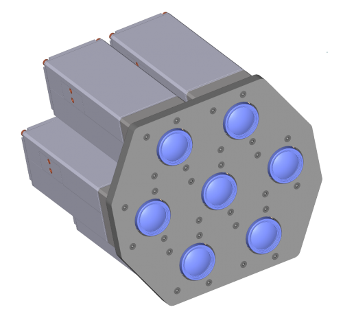 Last years we were working on the multi-sensor cameras and optical parts of the cameras. It all started as a temporary diversion from the development of the model 373 cameras that we planned to use instead of our current model 353 cameras based on the discontinued Axis CPU. The problem with the 373 design was that while the prototype was assembled and successfully tested (together with two new add-on boards) I did not like the bandwidth between the FPGA and the CPU – even as I used as many connection channels between them as possible. So while the Texas Instruments DaVinci processor was a significant upgrade to the camera CPU power, the camera design did not seem to me as being able to stay current for the next 3-5 years and being able to accommodate new emerging (not yet available) sensors with increased resolution and frame rate. This is why we decided to put that design on hold being ready to start the production if our the number of our stored Axis CPU would fall dangerously low. Meanwhile wait for the better CPU/FPGA integration options to appear and focus on the development of the other parts of the system that are really important.
Now that wait for the processor is nearly over and it seems to be just in time – we still have enough stock to be able to provide NC353 cameras until the replacement will be ready. I’ll get to this later in the post, and first tell where did we get during these 3 years.
Optical measurements, mechanical design, image processing and cameras calibration
Up until 2009 we did not really bother with the optics of the cameras we made – cameras have a standard CS-mount that can accommodate C- and CS-mount lenses, available from many suppliers. We provided the electronics and software, but it was up to our users to deal with the rest. Yes, we did offer cameras with color and monochrome sensors, with or without IR cutoff filters, stocked some basic varifocal lenses – but that was virtually all. When we started to develop panoramic cameras ourselves we quickly recognized that the lenses we need just do not exist. The C/CS-mount format lenses are too big to make a compact layout of the camera (it not only becomes big itself, but large distance between the lenses cause large parallax that makes panorama stitching more difficult). The smaller M12 mount lenses (also called “S-mount”, and “board lens”) are mostly designed for the small security cameras and being cost-sensitive are not usually designed for the top performance.
We also realized that putting together multiple individual cameras to cover a panorama is not enough. All camera lenses have best resolution in the center, while closer to the corners it degrades. In many, especially small lenses the corners are substantially darker due to vignetting. And while we got used to it making photographs – in many cases it was even be considered as a useful feature to focus on the object in the center and blur and fade out the periphery, in stitched panoramas it is a disaster, as the individual lenses peripheral areas will be mapped to the middle areas of the composite panorama image.
Not being the lens manufacturers ourselves we went the path of correcting the lens aberrations by software post-processing ( “Zoom in. Now… enhance.” and later posts) – that allowed us to effectively double number of lens “megapixels”. Later we used the same pattern we developed for aberration correction to precisely correct the lens distortions. This process of camera calibration for the spherical view camera is described in my previous blogs (such as Building and Calibrating Eyesis4π) – we started to do so for the precise panorama stitching but later worked on making it suitable for the stereo photogrammetry and 3d reconstruction.
So now we have what we believe is the highest performance camera of a kind – the one that we demonstrated at SIGGRAPH-2012. We also have now precise thermally-compensated sensor front end that can be used in other applications – in an individual camera or in multi-camera setups.
One such application is
Shallow depth of field and cinema cameras
For many years now Elphel was cooperating with a group of enthusiasts who tried to adapt our cameras to use for cinema applications – and that fits very well into our vision: take our cameras and use them as clay to form something you (not us) envision. But eventually they got tired of waiting for our next model 373 camera (that they needed to support higher frame rate and larger image sensor) so they decided to develop a new camera themselves.
One of the main camera features they (and others who are interested in the cinematographic applications) needed was the physically large sensor. Such sensors allow capturing images with “shallow” depth of field (DoF) and can be used to shoot video where some objects are in focus, while others (farther or closer) need to be blurred. With the single lens systems the scale of distances where you can use DoF depends on the physical size of the sensor and with the small sensor as we use (and those used in camera-phones) are approximately 5 times (linearly) smaller than the 35-mm film frame. So what you can achieve with 35mm camera in 5-10 meter range is only possible in the 1-2 meter range with the small 1/2.5″ (~7mm diagonal) sensor – so instead of the human actors you’ll have to make animation with dolls. There are even special optical adapters that use 35mm format lens to focus image on the diffusing screen (made of wax or even fast rotating disk to make diffusing grains smaller) and then transfer the image on that screen to the small format sensor of the inexpensive camcorder. But that system still had limited resolution and was loosing a lot of light, dramatically reducing the camera sensitivity.
The DoF first came as the feature inherent to the physical camera, the process of capturing the three-dimensional world on a two-dimensional media (film or image sensor). But in the artist’s hands it became a tool to focus viewer attention on the intended objects and also to show the 3-d nature of the actual world. With the modern computer animation there are no physical cameras with the lenses involved, but the depth of field is still present (like in this Sintel gallery). That means that the “shallow” DoF can be synthesized when the 3d information about the scene is present, and such information can be captured by other means – not only by the large format sensor and then the result image is rendered with synthetic depth of field. In some cases even a stereo-camera setup (a pair of synchronized cameras) can be used. Such setup is generally sufficient, if the in-focus objects are in foreground and there is nothing closer to the camera that occludes the target. But if such system is used to capture say image of a human behind the tree branches, then a single horizontal branch can close view of the human eye to both camera lenses. So regardless of how you blur the foreground objects (tree branches in this case) you will not be able to reconstruct the sharp image of the human face – there is no information about the color of the eye completely missing on both camera images. Using more cameras in the setup helps to provide more information about the objects – in our last case the third camera shifted vertically from the first two will have the information about the eye that was missing on the images from the first two cameras.
Building the 3-d model of the scene from the multiple images is not an easy task. The precision of the depth measurements is much lower than measuring distances in the direction orthogonal to the line of view. And often the portions of the scene have no fine details and so there is nothing to match to find out the distance to that object. On the other hand, when the 3-d reconstruction is needed just for synthesizing DoF, the precision of the distance needed to simulate the DoF of a real lens is the same as you can get from the lenses separated by the large lens diameter. The areas that do not have details, where it is impossible to measure distance – that areas would look the same on the final image, even if you blur them with the wrong sigma (or not blur at all).
HTML5 demo
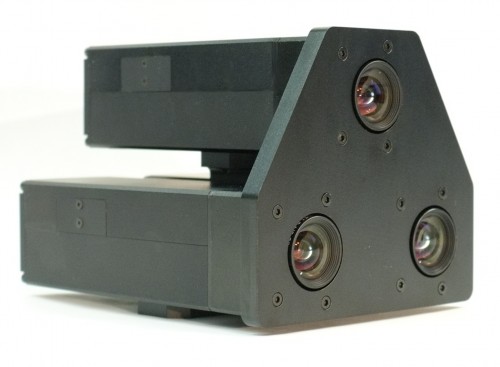
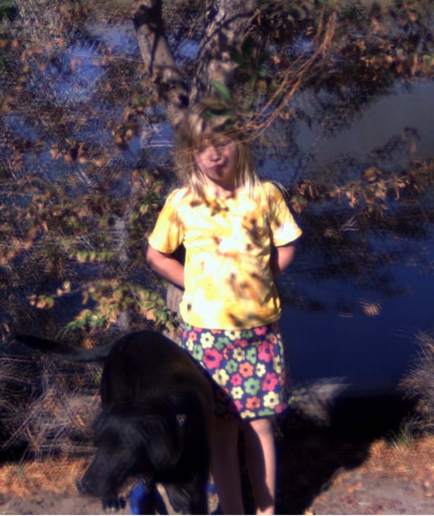
We do not yet have a seven-camera setup or “heptaclops”, we used a smaller “triclops” configuration. When we had built and calibrated the new camera (using the target pattern data measured earlier with Eyesis) we looked at the way to demonstrate it. First the images were processed with the known calibration and each of the raw images was mapped to the common projection plane – each pixel with ~0.15 pix accuracy – this process compensates for the lenses distortions and mis-alignment of the individual sub-cameras. These images can be used as the input data for the 3-d reconstruction. We do not have finished 3-d processing software yet, Oleg Dzhimiev made a small HTML5 application that illustrates the information from the camera triplet.
This web application overlaps the triplet of the corrected images acquired simultaneously by the 3 sub-cameras and applies the transparencies to the two of them so the the visible superposition has equal weight of each image of the set. Then each image is shifted by the value of the disparity that matches the distance from the camera to the image plane – the amount of disparity is controlled by a slider or by rotating the mouse scroll wheel. The objects in or near the selected image plane from all three images coincide, while the objects closer or farther from the camera are shifted from each other. When the shift is small, it looks like a blur, but farther images look as they actually are – as individual ones. While these separate image spoil illusion of the out-of-focus blurring (but still looking more realistic than dual images in old rangefinder cameras), they illustrate the raw data. Using more parallel cameras would improve illusion of focusing on such fast demo and provide more data for the actual reconstruction, reduce ambiguity when finding the disparity (and so the distance) at each pixel. Additionally, combining the data from multiple individual sensors would increase signal-to-noise ratio of the result image and so the dynamic range even if used with the same exposure/gain settings. And it is possible to program some channels with different exposure and run the whole system in the HDR mode.
The same applcation can be useful with the 3-d processing too. Instead of the 3 images that are just aberration and distortion corrected originals acquired from the different sensors, we can generate multiple close views and feed them to the same program – just shifting multiple images (or videos) is much less computationally demanding as correct 3-d rendering of the scene with the selected image plane and DoF, so such application can be used as a preview for the artist to dynamically adjust those parameters (distance and DoF) before running the final rendering (when it is possible to add desired bokeh too).
Back to the Model NC373 camera status
We decided to drop the idea of building the already designed and prototyped model NC373 camera. While the next camera will share some parts with the 373, the changes are too big to call it just a revision “C” of the 10373 system board, so it will be model NC393. The camera system board will have Xilinx Zynq that combines FPGA and a dual-core ARM processor on a same chip, so my main concern of the FPGA-CPU bandwidth is not applicable here.
When information about the new Xilinx device was announced, I thought it is a good candidate for the next camera design. In spring of the last year we had a Xilinx seminar in Salt Lake City, where I was told that these new devices will be supported by the zero-cost development software.
That feature is very important for us, because while the cost of the tools is not high for the manufacturer, it is higher than the cost of a camera. We strive to make our products highly customizable by the users, each camera contains the source code needed to compile the executables (including the FPGA code). Making our customers to pay high price to be able to modify even a single line of the FPGA code is not acceptable to us, so we use only those FPGA devices in our designs that are supported by the software that our users can download at zero cost. Of course ideally we would love to use free (FLOSS) development tools (like we use for the FPGA functional simulation), not just the zero cost ones, but in the real world it is not possible yet, so we develop and share our free (licensed under GNU GPLv3) code with the non-free closed-source tools.
The news that came from the Xilinx reps later last year were really disappointing – none of the Zynq devices (even the smallest one) will be supported by the zero-price software tools. And only this year it finally became official that 3 of the 4 devices is going to be supported and so we can use them. Xilinx did have some production delays, the availability schedule slipped to later dates, but I’m crossing my fingers that the needed part/package combination will actually be in production by the end of the Q1 2013.
While the NC393 design is far from being finished, some features are already settled and are likely to remain unchanged in the final product.
- The camera will be compatible with both parallel output sensors (such as the Aptina MT9P001/MP9P031/MP9P006 that we use currently) and the multi-lane serial sensors (such as having MIPI). The connectors will not change and the sensors used with NC353 will fit directly to the NC393 camera
- The camera system board is being designed for the multi-sensor operation. It will accommodate three sensors without the need to use multiplexer boards (like 10359 needed for NC353). Multiplexer boards will likely still be used in some cases, but the system board itself will have 3 identical sensor board connectors
- Physical dimensions of the camera and the mounting holes location on the system board will remain the same as on the previous camera models
- Camera will have a single GigE port as a main communication channel
- One serial console port with internal USB converter, so a microUSB cable will be sufficient to use system console for the software development.
- Firmware installation and update will be done by booting from the microSD accessible without opening of the camera. It will be possible to use the same card slot during normal operation for data storage.
- 512MB NAND flash as a main storage for firmware, boot source for camera normal operation.
- 1GB of the system memory made of the two 256×16 DDR3 chips.
- 512MB of dedicated video memory (not shared with the CPU) – one 256×16 DDR3 chip, same the one used for the system memory.
- USB2 (host): One external micro-USB and 2 internal flex cable connectors with USB, additional 3.3VDC power, I2C and FPGA general purpose I/O compatible withe the add-on boards for the NC353
- 30-pin board-to-board connector with 12 differential /24 single-ended FPGA I/O for add-on boards.
- a pair of 2.5mm audio connectors on the back panel for camera synchronization – from external trigger and/or from other cameras
- 2-port SATA controller based on the free (GNU/GPL) implementation. Camera will have eSATA/USB external connector (so capable of running external SATA device without additional power supply) and internal mSATA SSD that fits inside the camera.
Elphel will use the new system board in the Eyesis cameras. It will allow us to make the overall design more compact by reducing number of boards inside, increase the network bandwidth as well as the SSD bandwidth, increase the frame rate. We also plan to increase the camera resolution by switching to the same format but smaller pixel sensor while reusing the same optical-mechanical design – that would be definitely too much for the current system that is limited to the currently used sensors.
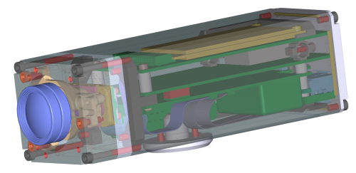
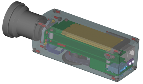
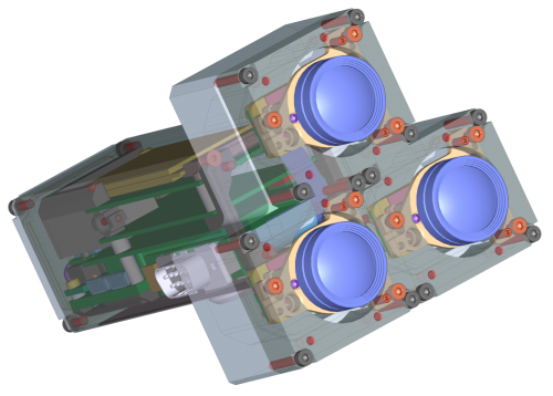
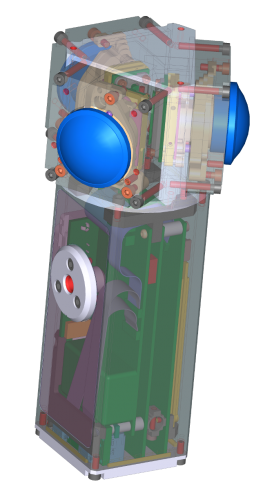
And of course we will continue to build “small” cameras based on the new design – with universal C/CS-mount and with M12 one, including precisely calibrated fixed-lens systems. And as the camera is designed for the multi-sensor operations, we will offer several typical configurations for robotic (parallel sensors for stereo-vision) and panoramic applications, as shown on the images above.
All the camera hardware documentation (circuit diagrams, parts lists, PCB layout and mechanical CAD files) will be released under CERN OHL license when the design will be finished and we will start the actual production of the cameras (add-on documentation will be released when it will become available) . All the firmware and FPGA code will be traditionally released under GNU GPL and maintained at Sourceforge repositories.
GREAT! 🙂
will the heightened capacity of the FPGA/CPU make possible to deliver the frames at 12 bits, either full sensor/image resolution or some resolution close the HD, at a reasonable speed (25fps)? will those developments, or some of them, be able to be back ported to the NC535?
Biel, thank you.
When we use JP4 mode with high compression quality the difference between the 12-bit sensor output and the decompressed camera footage is under the noise floor of the sensor, but you still get 3 to 5 times less data to store/transmit.
When you perform image/video editing, the lossless compression is a must, but with the camera there is not much sense to increase amount of data 3-5 times just to be able to reproduce the shot noise of each pixel better.
I tried to explain that in old LinuxDevices article (http://www3.elphel.com/linuxdevices/articles/AT9913651997.html ), but unfortunately images and javascript later got corrupted.
So even in the next higher performance cameras we will have compression (matching the sensor noise performance) and use the bandwidth for more sensors, higher resolution or higher frame rate. If we used non-compressed data in the 353 camera, we could only increase data rate (resolution*frame rate) some 50% if we used GigE instead of the current 100Mbps network.
Porting new developments to NC353 – well, so far we only use them with the NC353. Distortion corrections are probably possible for the video, but aberration corerction require very high compression quality, so it is not yet good for video – only for still images. So we worked on optical part and image processing, with the 393 we’ll be able to reuse it and apply to video.
Andrey
PS. The rest of our conversation is moved to the support mailing list
Been saying this for years Andrey. Good to see you picked up the ideas.
The three chip design does not pickup the center line, so it is possible to have a hole which depth is obscured to all three lens. First came up with this problem on a 3d system idea of mine maybe in the 80\’s I think. For cameras I concluded that a central view is best, which is highly inconvenient, because like this, I would prefer 3, or 4 corner, lens design, rather then chucking in a center lens for a 4, 5, or preferably 9 lens design. However, I am pursuing large lens 3d image recovery technique too, but optimal large lens format is over 6cm wide, as is stereoscopic lens spacing. So, I am picking among them depending on product purpose.
What is now needed however, is 4k+ at 48-60 progressive 3d frames a second. A fullhd raw level camera was the target in 2005. It is a shame they gave up waiting, but your cameras can still tap into their open source post software and supported format, which is good. I\’ve concluded that it is also a good strategy for me if I ever developed a camera myself. Some advanced technologies are potentially heading my way that can under cut and completely replace fpga, from friends, and my own designs.
BTW, in the meantime, you might like to investigate using Ambarella chips. I have not investigated the flexibility of their core comoressiin design, but they are starting to make arm Android version with advanced gpu acceleration that might be able to be used instead ti access raw frames. The only thing I remember about davinci, is how they compared. I think it would be hard to beat in fpga on the price.
Cheers.
Did you consider adding an F-mount version ?
No, Florent, we do not plan to use larger format lenses – we will stay with multiple small ones to achieve scalable resolution of the final video and the 3-d capabilities simultaneously.