This post continues discussion of the small tile space-variant frequency domain (FD) image processing in the camera, it demonstrates that modulated complex lapped transform (MCLT) of the Bayer mosaic color images requires almost 3 times less computational resources than that of the full RGB color data.
“Small Tile” and “Space Variant”
Why “small tile“? Most camera images have short (up to few pixels) correlation/mutual information span related to the acquisition system properties – optical aberrations cause a single scene object point influence a small area of the sensor pixels. When matching multiple images increase of the window size reduces the lateral (x,y) resolution, so many of the 3d reconstruction algorithms do not use any windows at all, and process every pixel individually. Other limitation on the window size comes from the fact that FD conversions (Fourier and similar) in Cartesian coordinates are shift-invariant, but are sensitive to scale and rotation mismatch. So targeting say 0.1 pixel disparity accuracy the scale mismatch should not cause error accumulation over window width exceeding that value. With 8×8 tiles (16×16 overlapped) acceptable scale mismatch (such as focal length variations) should be under 1%. That tolerance is reasonable, but it can not get much tighter.
What is “space variant“? One of the most universal operations performed in the FD is convolution (also related to correlation) that exploits convolution-multiplication property. Mathematically convolution applies the same operation to each of the points of the source data, so shifted object of the source image produces just a shifted result after convolution. In the physical world it is a close approximation, but not an exact one. Stars imaged by a telescope may have sharper images in the center, but more blurred in the peripheral areas. While close (angularly) stars produce almost the same shape images, the far ones do not. This does not invalidate convolution approach completely, but requires kernel to (smoothly) vary over the input images [1, 2], makes it a space-variant kernel.
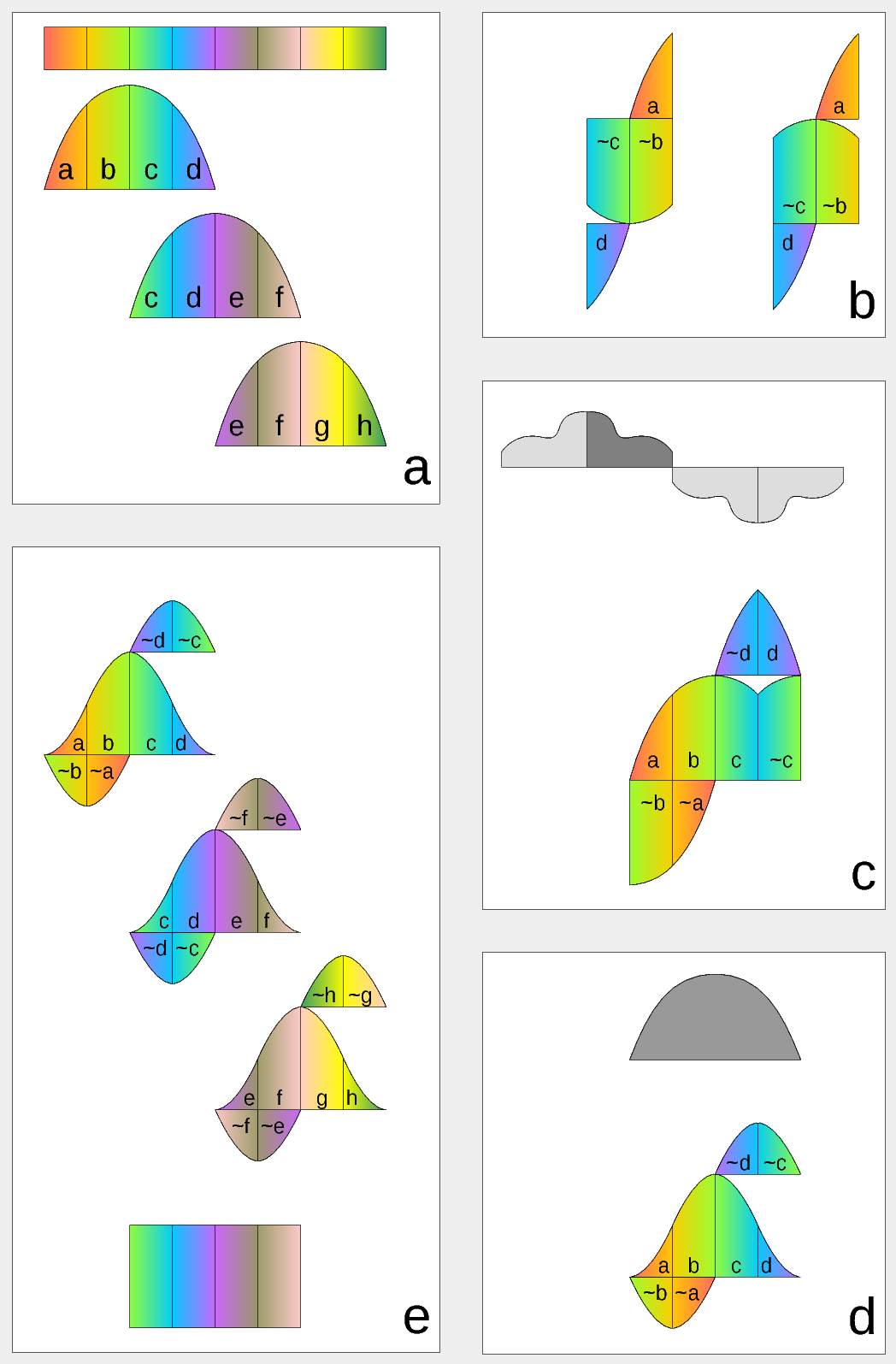
Figure 1. Complex Lapped Transform with DCT-IV/DST-IV: time-domain aliasing cancellation (TDAC) property. a) selection of overlapping input subsequences 2*N-long, multiplication by sine window; b) creating N-long sequences for DCT-IV (left) and DST-IV (right); c) (after frequency domain processing) extending N-long sequence using DCT-IV boundary conditions (DST-IV processing is similar); d) second multiplication by sine window; e) combining partial data
There is another issue related to the space-variant kernels. Fractional pixel shifts are required for multiple steps of the processing: aberration correction (obvious in the case of the lateral chromatic aberration), image rectification before matching that accounts for lens optical distortion, camera orientation mismatch and epipolar geometry transformations. Traditionally it is handled by the image rectification that involves re-sampling of the pixel values for a new grid using some type of the interpolation. This process distorts the signal data and introduces non-linear errors that reduce accuracy of the correlation, that is important for subpixel disparity measurements. Our approach completely eliminates resampling and combines integer pixel shift in the pixel domain and delegates the residual fractional pixel shift (±0.5 pix) to the FD, where it is implemented as a cosine/sine phase rotator. Multiple sources of the required pixel shift are combined for each tile, and then a single phase rotation is performed as a last step of pixel domain to FD conversion.
Frequency Domain Conversion with the Modulated Complex Lapped Transform
Modulated Complex Lapped Transform (MCLT)[3] can be used to split input sequence into overlapping fractions, processed separately and then recombined without block artifacts. Popular application is the signal compression where “processed separately” means compressed by the encoder (may be lossy) and then reconstructed by the decoder. MCLT is similar to the MDCT that is implemented with DCT-IV, but it additionally preserves and allows frequency domain modification of the signal phase. This feature is required for our application (fractional pixel shifts and asymmetrical lens aberrations modify phase), and MCLT includes both MDCT and MDST (that use DCT-IV and DST-IV respectively). For the image processing (2d conversion) four sub-transforms are needed:
It is a common case when a company or organization uses multiple content management systems (CMS) and specialized web application to organize its web presence. We describe here how Elphel handles such CMS variety and provide the source code that can be customized for other similar sites.
(more…)
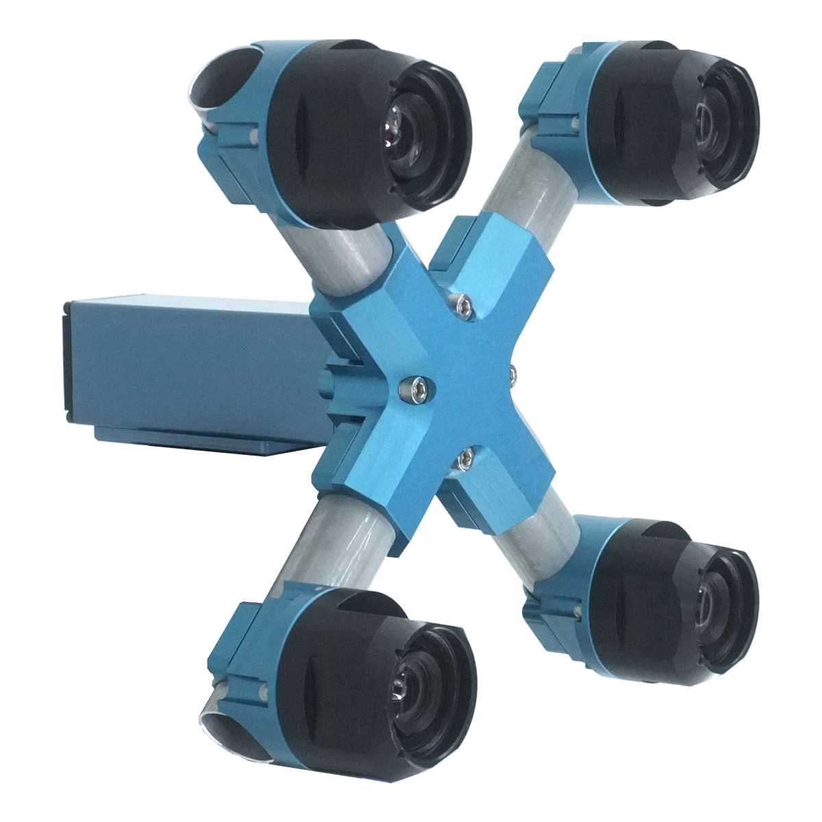
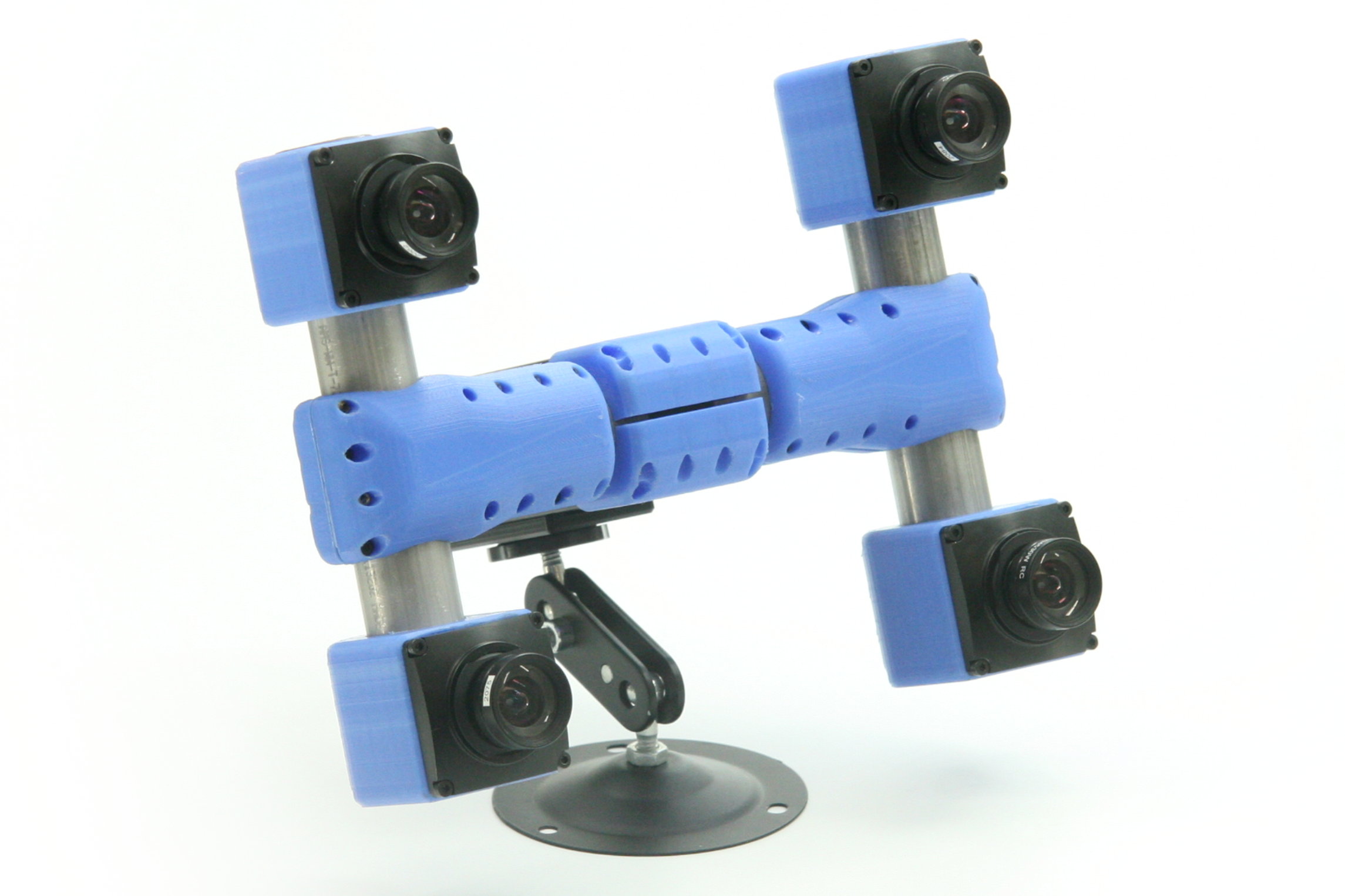
Four-camera stereo rig prototype is capable of measuring distances thousands times exceeding the camera baseline over wide (60 by 45 degrees) field of view. With 150 mm distance between lenses it provides ranging data at 200 meters with 10% accuracy, production units will have higher accuracy. Initial implementation uses software post-processing, but the core part of the software (tile processor) is designed as FPGA simulation and will be moved to the actual FPGA of the camera for the real time applications.
Scroll down or just hyper-jump to Scene viewer for the links to see example images and reconstructed scenes.(more…)
Fig.1. Image comparison of the different processing stages output
Results of the processing of the color image
Previous blog post “Lens aberration correction with the lapped MDCT” described our experiments with the lapped MDCT[1] for optical aberration corrections of a single color channel and separation of the asymmetrical kernel into a small asymmetrical part for direct convolution and a larger symmetrical one to be applied in the frequency domain of the MDCT. We supplemented this processing chain with additional steps of the image conditioning to evaluate the overall quality of the of the results and feasibility of the MDCT approach for processing in the camera FPGA.
Image comparator in Fig.1 allows to see the difference between the images generated from the results of the several stages of the processing. It makes possible to compare any two of the image layers by either sliding the image separator or by just clicking on the image – that alternates right/left images. Zoom is controlled by the scroll wheel (click on the zoom indicator fits image), pan – by dragging.
Original image was acquired with Elphel model 393 camera with 5 Mpix MT9P006 image sensor and Sunex DSL227 fisheye lens, saved in jp4 format as a raw Bayer data at 98% compression quality. Calibration was performed with the Java program using calibration pattern visible in the image itself. The program is designed to work with the low-distortion lenses so fisheye was a stretch and the calibration kernels near the edges are just replicated from the ones closer to the center, so aberration correction is only partial in those areas.
First two layers differ just by added annotations, they both show output of a simple bilinear demosaic processing, same as generated by the camera when running in JPEG mode. Next layers show different stages of the processing, details are provided later in this blog post.
(more…)
Modern small-pixel image sensors exceed resolution of the lenses, so it is the optics of the camera, not the raw sensor “megapixels” that define how sharp are the images, especially in the off-center areas. Multi-sensor camera systems that depend on the tiled images do not have any center areas, so overall system resolution may be as low as that of is its worst part.
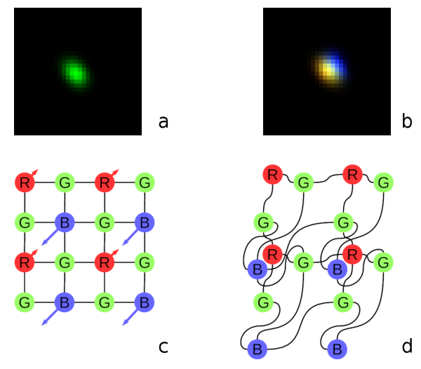
Fig. 1. Lateral chromatic aberration and Bayer mosaic: a) monochrome (green) PSF, b) composite color PSF, c) Bayer mosaic of the sensor, d) distorted mosaic for the chromatic aberration of b).
De-mosaic processing and chromatic aberrations
Our current cameras role is to preserve the raw sensor data while providing some moderate compression, all the image correction is applied during post-processing. Handling the lens aberration has to be done before color conversion (or de-mosaicing). When converting Bayer data to color images most cameras start with the calculation of the “missing” colors in the RG/GB pattern using 3×3 or 5×5 kernels, this procedure relies on the specific arrangement of the color filters.
Each of the red and blue pixels has 4 green ones at the same distance (pixel pitch) and 4 of the opposite (R for B and B for R) color at the equidistant diagonal locations. Fig.1. shows how lateral chromatic aberration disturbs these relations.
Fig.1a is the point-spread function (PSF) of the green channel of the sensor. The resolution of the PSF measurement is twice higher than the pixel pitch, so the lens is not that bad – horizontal distance between the 2 greens in Fig.1c corresponds to 4 pixels of Fig.1a. It is also clearly visible that the PSF is elongated and the radial resolution in this part of the image is better than the tangential one (lens center is left-down).
Fig.1b shows superposition of the 3 color channels: blue center is shifted up-and-right by approximately 2 PSF pixels (so one actual pixel period of the sensor) and the red one – half-pixel left-and-down from the green center. So the point light of a star, centered around some green pixel will not just spread uniformly to the two “R”s and two “B”s shown connected with lines in Fig.1c, but the other ones and in different order. Fig.1d illustrates the effective positions of the sensor pixels that match the lens aberration.
(more…)
As we finished with the basic camera functionality and tested the first Eyesis4π built with the new 10393 system boards (it is smaller, requires less power and, is faster) we are moving forward with the in-camera image processing. We plan to combine our current camera calibration methods that require off-line post processing and the real-time image correction using the camera own FPGA resources. This project development will require switching between the actual FPGA coding and the software implementation of the same algorithms before going to the next step – software is still easier to design. The first part was in FPGA realm – it was to implement the fundamental image processing block that we already know we’ll be using and see how much of the resources it needs.
DCT type IV as a building block for in-camera image processing
We consider a small (8×8 pixel) DCT-IV to be a universal block for conditioning of the raw acquired images. Such operations as lens optical aberrations correction, color conversion (de-mosaic) in the presence of the lateral chromatic aberration, image rectification (de-warping) are easier to perform in the frequency domain using convolution-multiplication property and other algorithms.
In post-processing we use DFT (Discrete Fourier Transform) over rather large (64×64 to 512×512) tiles, but that would be too much for the in-camera processing. First is the tile size – for good lenses we do not need that large convolution kernels. Additionally we plan to combine several processing steps into one (based on our off-line post-processing experience) and so we do not need to sub-sample images – in our current software we double resolution of the raw images at the beginning and scale back the final result to reduce image degradation caused by re-sampling.
The second area where we plan to reduce computations is the replacement of the DFT with the DCT that is designed to be fed with the pure real data and so requires less arithmetic operations than DFT that processes complex input values.
Why “type IV” of the DCT?
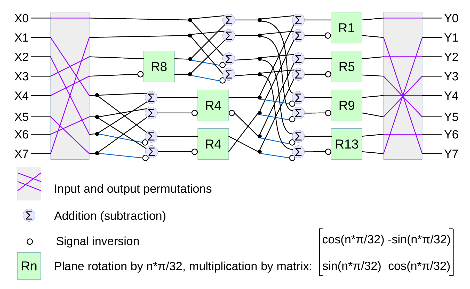
Fig.1. Signal flow graph for DCT-IV
We already have DCT type II implemented for the JPEG/JP4 compression, and we still needed another one. Type IV is used in audio compression because it can be converted to a modified discrete cosine transform (MDCT) – a procedure when multiple overlapped windows are processed one at a time and the results are seamlessly combined without any block artifacts that are familiar for the JPEG with low settings of the compression quality. We too need lapped transform to process large images with relatively small (much smaller than the image itself) convolution kernels, and DCT-IV is a perfect fit. 8-point DCT-IV allows to implement transformation of 16-point segments with 8-point overlap in a reversible manner – the inverse transformation of 8-point data may be converted to 16-point overlapping segments, and being added together these segments result in the original data.
(more…)
Since we started to deliver first NC393 series cameras in May we were working on the cameras software – original version was rather limited. While it was capable of serving images/video over the network and recording them on the internal m.2 SSD, it did not have the advanced image acquisition control (through the GUI and programmatically) that was standard for the earlier NC353 series. Now the core functionality is operational and in a month we plan to have the remaining parts (inter-camera synchronization, working with multiple sensors per-port with 10359 multiplexer, GPS+IMU logging) online too. FPGA code is already ported, but it needs to be tested and a fair amount of troubleshooting, identifying the problems and weeding out the bugs is still left to be done.
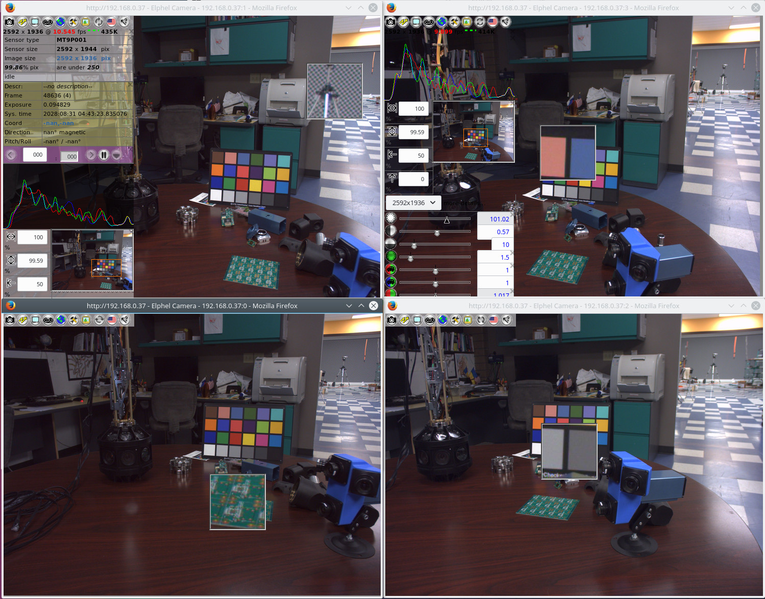
Fig 1. Four camvc instances for the four channels of NC393 camera
Users of earlier Elphel cameras can easily recognize familiar camvc web interface – Fig. 1 shows a screenshot of the four instances of this interface controlling 4 sensors of NC393 camera in “H” configuration.
(more…)
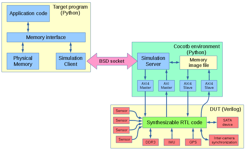
Or at least larger (verification) part of it – interfaces, packages and a few other synthesizable features are very useful to reduce size of Verilog code and make it easier to maintain. We now are able to run production target system Python code with Cocotb simulation over BSD sockets.
Client-server simulation of NC393 with Cocotb
Previous workflow
Before switching to Cocotb our FPGA-related workflow involved:
Creating RTL design code
Writing Verilog tests
Running simulations
Synthesizing and creating bitfile
Re-writing test code to run on the target system in Python
Developing kernel drivers to support the FPGA functionality
Developing applications that access FPGA functionality through the kernel drivers
Of course the steps are not that linear, there are hundreds of loops between steps 1 and 3 (editing RTL source after finding errors at step 3), almost as many from 5 to 1 (when the problems reveal themselves during hardware testing) but few are noticed only at step 6 or 7. Steps 2, 5, 6+7 involve a gross violation of DRY principle, especially the first two. The last steps sufficiently differ from step 5 as their purpose is different – while Python tests are made to reveal the potential problems including infrequent conditions, drivers only use a subset of functionality and try to “hide” problems – perform recovering actions to maintain operation of the device after abnormal condition occurs.
(more…)
Elphel cameras offer unique capabilities – they are high performance systems out of the box and have all the firmware and FPGA code distributed under GNU General Public Licenses making it possible for users to modify any part of the code. The project does not use any “black boxes” or encrypted modules, so it is simulated with the free software tools and user has access to every net in the design. We are trying to do our best to make this ‘hackability’ not just a theoretical possibility, but a practical one.
Current camera FPGA project contains over 400 files under version control and almost 100K lines of HDL (Verilog) code, there are also constraints files, tool configurations, so we need to provide means for convenient navigation and modification of the project by the users.
We are starting a series of tutorials to facilitate acquaintance with this project, and here is the first one that shows how to install and configure the software. This tutorial is made with a fresh Kubuntu 16.04 LTS distribution installed on a virtual machine – this flavor of GNU/Linux we use ourselves and so it is easier for us to help others in the case of problems, but it should be also easy to install it on other GNU/Linux systems.
Later we plan to show how to navigate code and view/modify tool parameters with VDT plugin, run simulation and implementation tools. Next will be a “Hello world” module added to the camera code base, then some simple module that accesses the video memory.
Video resolution is 1600×900 pixels, so full screen view is recommended.
Download links for: video and captions.
Running this software does not require to have an actual camera, so it may help our potential users to evaluate software capabilities and see if it matches their requirements before purchasing an actual hardware. We will also be able to provide remote access to the cameras in our office for experimenting with them.
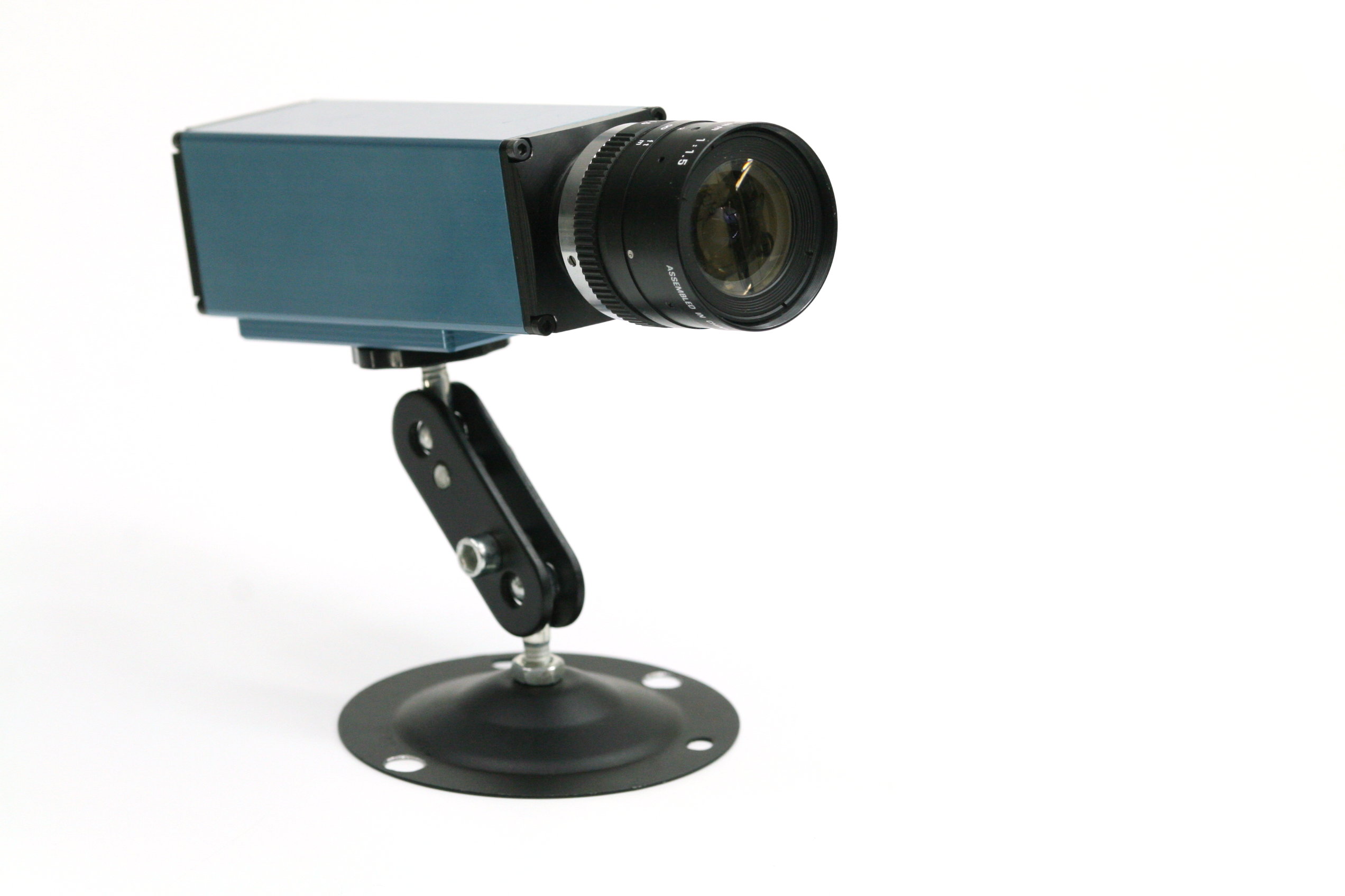
Two weeks ago we were making photos of our first production NC393 camera to post an announcement of the new product availability. We got all the mechanical parts and most of the electronic boards (14MPix version will be available shortly) and put them together. Nice looking camera, powered by a high performance SoC (dual ARM plus FPGA), packaged in a lightweight aluminum extrusion body, providing different options for various environments – indoors, outdoors, on board of the UAV or even in the open space with no air (cooling is important when you run most of the FPGA resources at full speed). Tons of potential possibilities, but the finished camera did not seem too exciting – there are so many similar looking devices available.
NC393 camera, front view
NC393 camera, back panel view. Includes DC power input (12-36V and 20-75V options), GigE, microSD card (bootable), microUSB(type B) connector for a system console with reset and boot source selection, USB/eSATA combo connector, microUSB(type A) and 2.5mm 4-contact barrel connector for external synchronization I/O
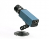
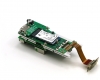
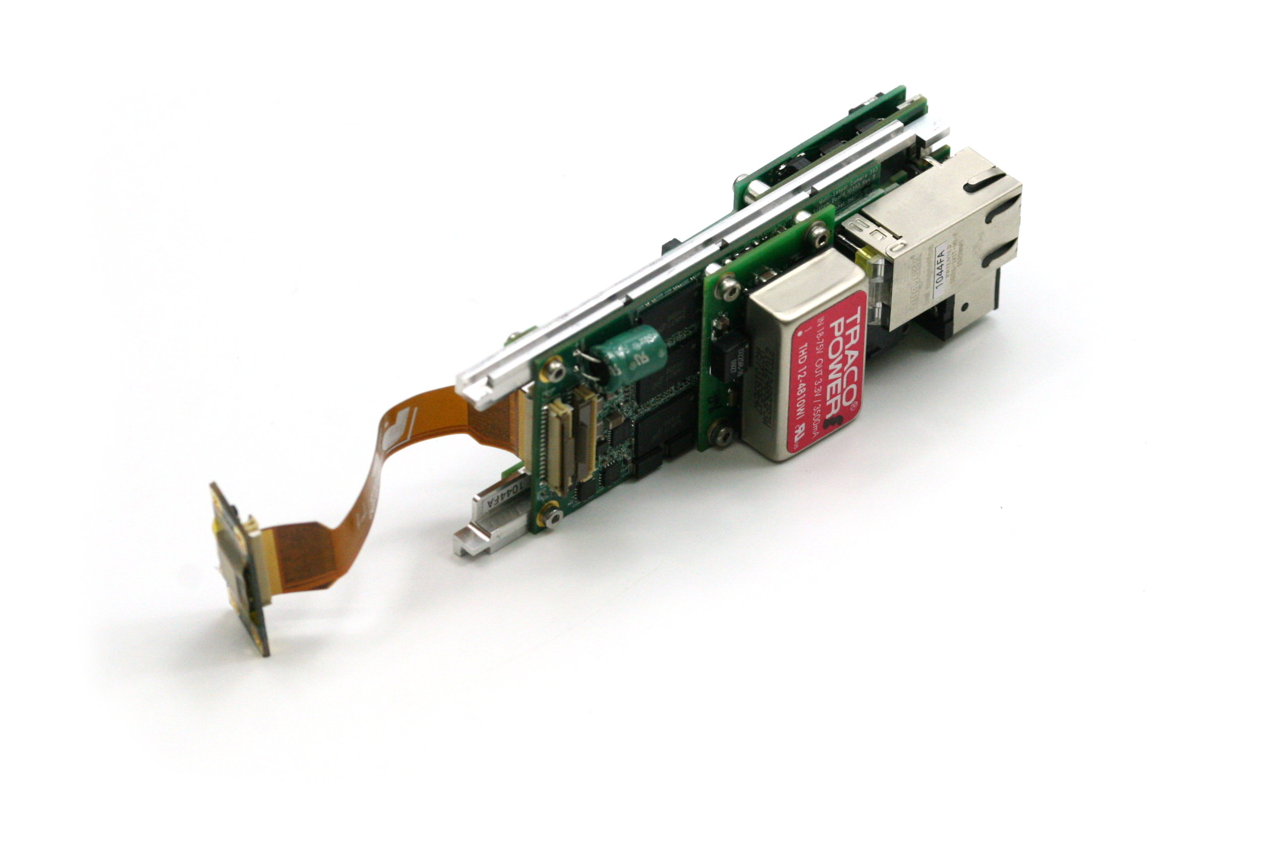
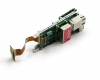
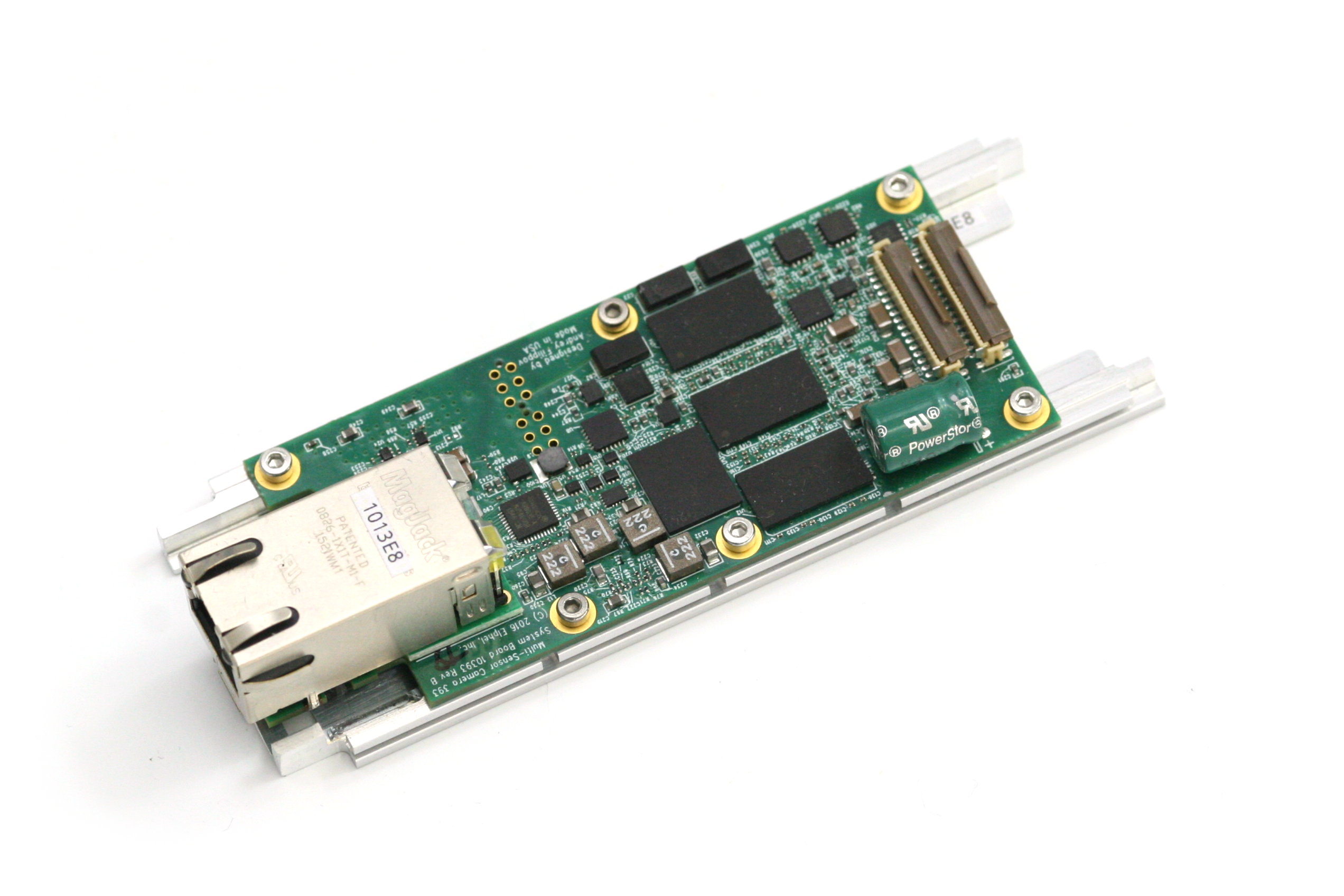
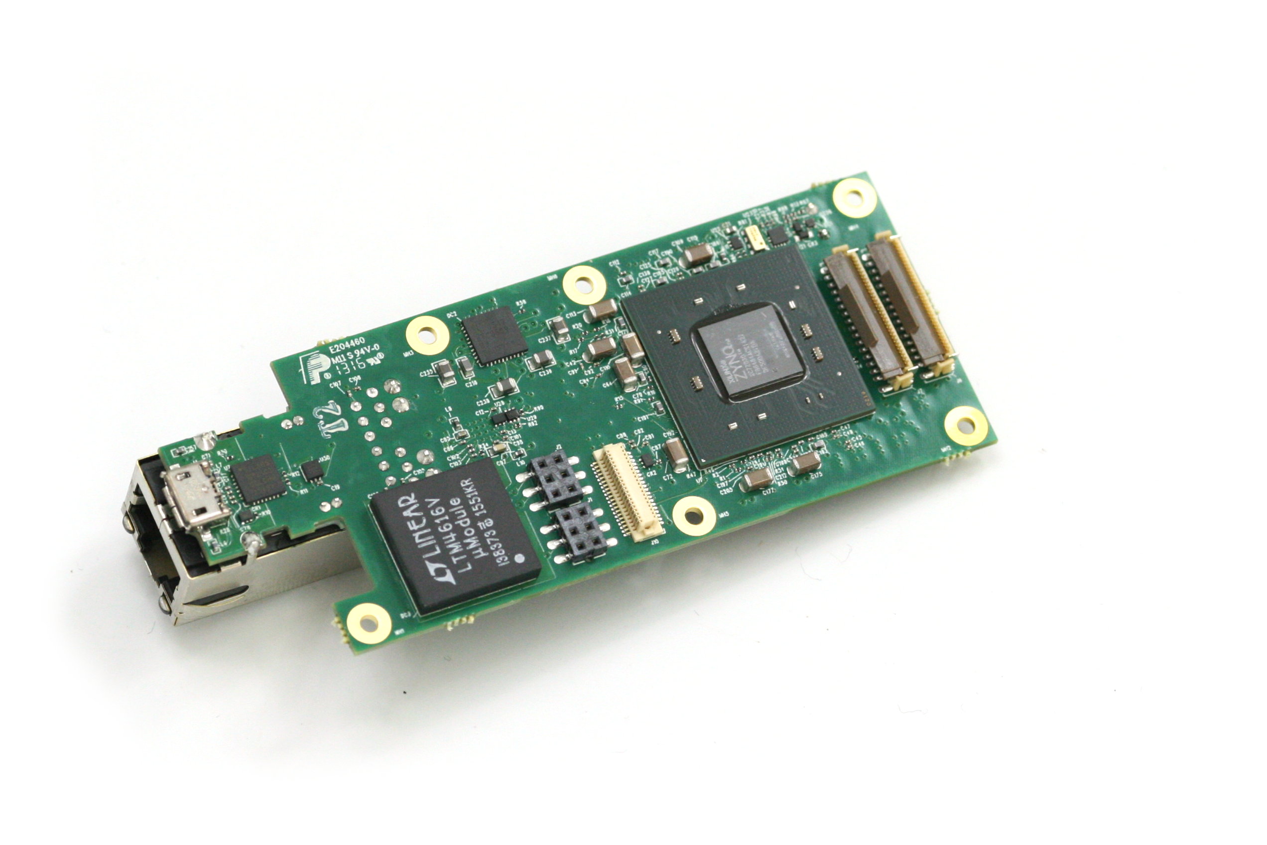
NC393 assembled boards: 10393(system board), 10385 (power supply board), 10389(interface board), 10338e (sensor board) and 103891 - synchronization adapter board, view from 10389. m.2 2242 SSD shown, bracket for the 2260 format provided. 10389 internal connectors include inter-camera synchronization and two of 3.3VDC+5.0VDC+I2C+USB ones.
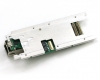
10393 system board attached to the heat frame, view from the heat frame. There is a large aluminum heat spreader attached to the other side of the frame with thermal conductive epoxy that provides heat transfer from the CPU without the use of any spring load. Other heat dissipating components use heat pads.
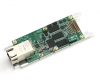
10393 system board attached to the heat frame, view from the 10393 board
10393 system board, view from the processor side
An obvious reason for our dissatisfaction is that the single-sensor camera uses just one of four available sensor ports. Of course it is possible to use more of the freed FPGA resources for a single image processing, but it is not what you can use out of the box. Many of our users buy camera components and arrange them in their custom setup themselves – that does not have a single-sensor limitation and it matches our goals – make it easy to develop a custom system, or sculpture the camera to meet your ideas as stated on our web site. We would like to open the cameras to those who do not have capabilities of advanced mechanical design and manufacturing or just want to try new camera ideas immediately after receiving the product.
(more…)

