Eyesis-4pi
Current state of the Eyesis project,
what worked and what did not. Or worked not as good as we would like it to
Most of the last year we spent developing Eyesis panoramic cameras, designing and then assembling the hardware, working on the software for image acquisition and processing. It was and continues to be a very interesting project, we had to confront multiple technical challenges, come up with the solutions we never tried before at Elphel – many of these efforts are documented in this blog.
We had built and shipped to the customers several Eyesis cameras, leaving one for ourselves, so we can use it for development of the new code and testing performance of the camera as a whole and the individual components. Most things worked as we wanted them to, but after building and operating the first revision of Eyesis we understood that some parts should be made differently.
What worked:
- Overall camera optical-mechanical composition, with the new sensor boards and compact M12 lenses (instead of the C/CS-mount ones we used before) we were able to achieve small (for this type of cameras) parallax ~34.5 mm between the entrance pupils of the adjacent lenses (90 mm for the opposite ones)
- Usage of the multiplexer boards to reduce the complexity of the system – each three camera sensor boards required just one set of the system boards (10353E), interface boards (10369A) and the multiplexer (10359A) ones, one mass storage device.
- Inter-camera synchronization – each of the three SFE attached to the same multiplexer boards are synchronized by that board, three composite camera modules are synchronized using the dedicated hardware ports, current FPGA code propagates the complete timestamp info from the “master” cameras. Programmable delay generators combined with the flexible sensor control allow implementation of the different triggering sequences.
- Lens aberration correction made it possible to improve sharpness of the images, especially important in off-center areas of each sub-camera. It was achieved by individual calibration of camera lenses over the full field of view, then inverting the effect of the aberrations during post-processing.
What did not work:
- Recording to the hard drives. The fastest data link from the camera is SATA and we are limited to the cable length (1 meter), so the drives have to be mounted near the camera head, not in the car. The vibrations in the data storage box attached to the camera mount tube were too high, so we were getting sporadic HDD failures. That happened only at high driving speed (above 65-70mph), above what is normally used for imaging, but we still decided to switch to the solid state devices – that of course eliminated the problem (though it is more expensive solution).
What needs improvement
Replacing the HDD with SSD was easy and did not require any redesign of the camera. Other issues need modification of the camera components.
- Insufficient range of the sensor board tilt adjustment to the lens optical axis. It needed to be just about twice larger to be able to compensate for most sensor chip misalignments, with the original design we had to remove the sensor front ends (SFE) from the adjustment setup, add shims under the corners of the SFE PCB and re-run the procedure. The results of the adjustment were very good (and we verified that the focus stayed unchanged under vibrations and varying temperatures), but the need for the shims made it very time consuming. It was not possible to correct the problem in the existent design, so we had to redesign the SFE parts for the next cameras to be built.
- Reduced resolution around zenith. Eyesis uses eight horizontally pointed f=4.5mm lenses with FOV 45°(horizontal) x 60°(vertical) and one fisheye lens (f=2.0mm) pointed up with a circular FOV 60° around zenith (120° total), so the angular resolution is 2.2 times less than that of the horizontal lenses. It is five times less if compared megapixels per steradian (worst-case values): 4.2 MPix/steradian for the horizontal sensors, only 0.83MPix/steradian for the top one.
- Stitching mismatch between the eight horizontal images and the top fisheye one, caused by the electronic rolling shutter (ERS) of the sensors. The horizontal images do not have such problems between themselves.
Updating the SFE adjustment module was not very difficult and during that redesign we simplified the SFE by making it one-time adjustable with an external device. New design is simpler and the parts are easier to manufacture. Improvement of the resolution in zenith and eliminating stitching artifacts related to the ERS required more radical changes. To explain the nature of those stitching problems, let me start with
Why does Elphel use CMOS sensors with Electronic Rolling Shutter (ERS)?
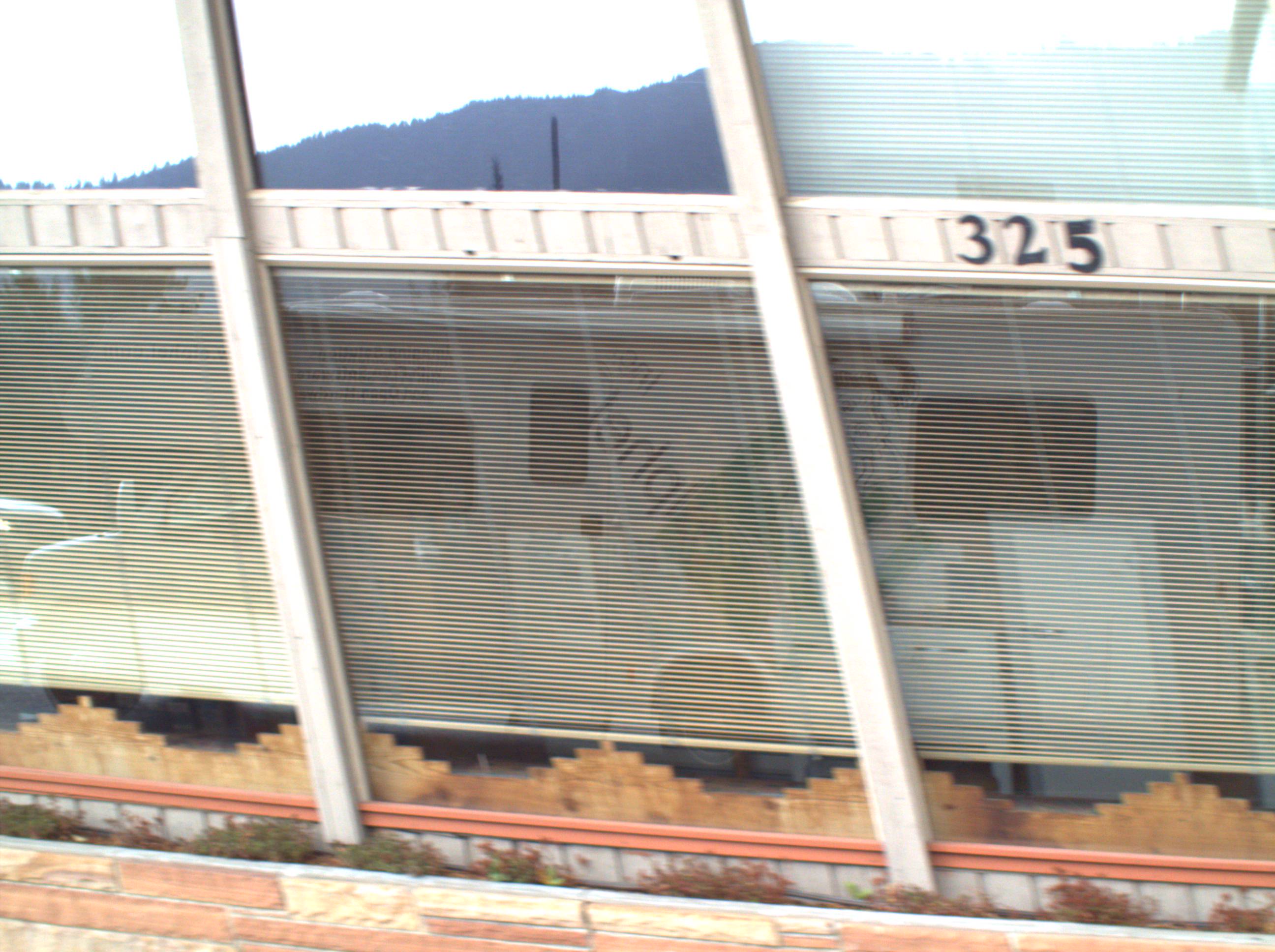
Commonly the ERS is considered bad, as something universally inferior to the global (“snapshot”) shutter, as a feature of the inexpensive sensors. Yes, the ERS causes distortions in many cases because different sensor scan lines are exposed at different times. That leads to tilting of the vertical lines when photographed from the moving vehicle, you can see our example of this effect. You may notice that the reflection of the vehicle (where the camera is mounted) in the distorted windows of the building is straight as it does not move in the camera view.
CMOS sensors with ERS have some advantages over other existent devices that do not exhibit similar distortions, these advantages are important for our application. Let us consider these alternatives:
- CCD with “electronic shutter”
- CMOS with “global shutter”
- CCD/CMOS with external shutter (usually mechanical, but LCD and other possible)
The CCD with fast electronic shutter (interline CCD) have the CCD registers that are used for transferring the pixel data (in the form of the electrical charges) from their original locations to the chip output(s). The registers are protected from the light, separate photosensitive elements (photodiodes) are located between them. After exposure ends, the charges from the diodes (proportional to the image pixel values) are simultaneously transferred to the elements of the CCD analog shift registers, they are then traveling over the sensor surface to the outputs that are the bottlenecks of the process – the full sensor readout time maybe rather long, especially for the high resolution sensors. The minimal readout time of the full sensor is the parameter that can be calculated from the specified maximal frame rate of the imager. Older CCD sensors used the CCD registers themselves as the photosensitive elements, they had just one half covered with non-transparent aluminum layer, so after the exposure the pixels where transferred at the high rate to the protected locations, the whole image was shifted under the shield. That did not work with short exposures because even the “fast forward” speed was limited, and the larger are the sensors, the longer it takes to shift the whole image.
The interline CCD are not completely scalable, because of the limits of the “shutter ratio”. When the pixels get smaller (and they have to shrink so more will fit on a reasonable size chip) it is more and more difficult to protect the CCD registers from light while having the open photodiodes close by, and some light gets to the CCD registers directly, bypassing the shutter. That leads to vertical smear of the image, because in addition to the intended charge each pixel gets some during the travel in the “vertical” registers (in the generic CCD readout process all pixels move up one step simultaneously, then the whole top row moves horizontally to the output and the process repeats). That effect is less visible on the relatively small (video) sensors, but it was definitely a problem with high resolution (11MPix) Kodak KAI-11002 that we used in models 323 and 363 cameras. When the exposure was above the 1/100 sec everything was perfect, but in the range of 1/100 to 1/1000 the light leak effect became visible, exposures shorter than 1/1000 always suffered from it. Of course the most noticeable it was in the high contrast images, i.e. having the Sun somewhere in the image produced a vertical column – all the pixels that travel over the bright spot on the sensor surface after (and before) the exposure were getting an extra signal. Smaller columns would appear from the reflections or lights. If the image is stationary, it is possible to correct that effect in software, but short exposures are usually needed when the objects or camera are moving fast and such correction can not work well.
The CMOS sensors with global shutters do not involve pixel chargers slowly moving over the imager as in the case of the CCD, but as the sensor output is still the readout bottleneck (sometimes there are multiple outputs), the pixels have to rely on some form of the analog memory and wait for their turn to be digitized and output. With the limited shutter ratio in the case of the high density sensors, some unwanted light can get to that analog memory (capacitor) and the recorded image will be a superposition of the ideal one and (reduced in shutter ratio times) image as if acquired with the exposure time equal to readout wait time (varying from zero for the pixels that are readout first to the full readout time for those readout last). That effect degrades the quality of the images, adds some motion blur to the result.
So with the existent global shutter CMOS sensors the result is similar to that of the CCD – with smaller sensors (~<1MPix) electronic global shutters work nicely, with the larger – their limitations begin to reveal themselves. This is why most of the high-resolution cameras make clicking sound at exposure – they have to use old-style mechanical shutters. And mechanical shutters have well known limitations of limited speed and/or lifetime. The LCD shutters have only 50% transparency when open, that is a huge waste of the precious photons. It is possible to use a combined fast electronic and slower mechanical shutter as we did in the 363 camera – slower mechanical shutter can survive longer.
The ERS sensors do not rely on the pixel analog memory (longer than the exposure itself), each pixel is readout immediately after the exposure ends. So while these sensors may produce distorted images, they do not suffer from image degrading caused by the light leak to the memory capacitors common the the most snapshot-shutter devices, even in the case of the high resolution ones. And in some cases there are ways to mitigate the distortion effects.
Probably ideal would be a combined CMOS sensor+ SDRAM memory on the same chip so each sensor line will be digitized and stored simultaneously in the memory (one ADC per line is already common in CMOS sensors), the memory contents can be read out sequentially. In that case the sensor would not depend on the analog memory and the performance would combine the shutter ratio of the ERS sensors with the snapshot operation. Unfortunately I do not yet know of any such sensors produced.
Reducing the ERS distortions

ERS distortions, horizontal sensor scan lines (from top to the bottom of the image). The vertical features of the cars moving in the opposite directions are tilted opposite too.
Note: image is captured with the telephoto lens to exaggerate distortions, not with Eyesis camera
There are different cases when the ERS distortions can be either eliminated or significantly reduced by post-processing images. If the most distortions are caused by rotation of the camera (i.e. making a photo with a cell phone camera) the correction can be done by using the inertial sensors data. Unfortunately that simple approach would not work for the fast moving camera, i.e. camera mounted on a car roof – that would require not just the data for the camera position and orientation over time, but also distances to each object (closer objects will be distorted more). And even in that case there still would be some problems, because moving closer objects over the far (little-distorted) background would leave voids on the result images, other images would be needed to fill them.
In the case of the camera attached to the car there are virtually no distortions caused by random fast angular rotations of the camera, like in the case of using a consumer camera without the tripod. That is true, of course, if the vehicle is not moving too fast on a poor road, if it does – inertial correction can be used. The main source of distortion is the apparent horizontal movement of the objects in the camera field of view – the closest objects move faster and are distorted more, the farther ones – move less and are less distorted. The most visible part of the distortion is that vertical lines look tilted, the right angles between vertical and horizontal features are not are not 90° on the image. The visual effect can be mitigated by using cameras in portrait mode, when the sensor scan lines are vertical. In that case the ERS distortion would result in just horizontally shrinking or expanding the close objects (depending on the sensor scan direction relative to the vehicle movement direction), i.e. close standing people would look either thinner or fatter. This effect is much less noticeable than tilted vertical features, and usually can be tolerated. Anyway in the crowded places, where people can get close to the camera, the camera will likely not be able to move fast, while most of the close features that are likely to be photographed at short range while camera with the vehicle are moving fast would not be important and the distortion would not be noticable.

ERS distortions, vertical sensor scan lines (from left to right of the image). The car moving from left to right is stretched horizontally, the one moving from right to left (yes, it is moving backwards sitting on top of the truck) is contracted horizontally.
Note: image is captured with the telephoto lens to exaggerate distortions, not with Eyesis camera
When using multiple cameras in portrait mode to capture a panoramic composite image, there is another challenge caused by the ERS operation of the sensors. If all the sub-cameras are fired simultaneously and scanning is in the same direction, the overlapping areas of each pair of the adjacent images would be acquired at different time, the effect would be as if the camera had huge parallax – the effective inter-camera distance would be the vehicle speed multiplied by the frame readout time. For the moderate speed of 45mph (72 km/h) and the 5MPix sensor we use (frame readout time= 1/15sec) that distance would be 1.3m – nearly 40 times exceeding the camera actual parallax, caused by the different lenses locations. That obviously means that the overlapping areas of the images have to be acquired at the same time.
The US patent 7834910 suggests splitting sub-cameras in pairs (right/left for the vehicle) and firing each half of them one after another, so when the two (right/left) front cameras finished scanning (starting from the common direction forward), the next pair starts from the same overlapping area of the composite panorama image, where the previous cameras finished. The same repeats with the next pair of cameras, and so on until the last cameras meet scanning in exactly the backward direction. That approach is possible, but as the the number of cameras increases, the total effective parallax between the front and back looking cameras increases even more. Another possible solution is to alternate the direction of scanning for each adjacent cameras so they all are fired simultaneously. That would cause the alternation of “fatter”/”thinner” people images,but the total composite parallax caused by the ERS and vehicle movement would still be limited to that of a single sub-camera.

FOV of sub-cameras in Eyesis, color shows time of acquisition (from red to blue)
The top sensor with a fisheye lens in the original Eyesis camera was selected knowingly sacrificing the resolution in that segment to reduce the total number of sub-cameras in the system. In most cases there is nothing above 30° up from the horizon but the sky, so the sharp images there would not add much information. When sacrificing the resolution we also knew that there could be some stitching mismatch between the horizontally pointed sub-cameras and the top fisheye one. Such mismatch could be reduced with the arrangement described in the mentioned patent and slowing the scanning of the fisheye sensor to approximately match that of the combined horizontal ones. That solution would still not provide a perfect match in the stitching areas because it would require variable scanning speed that is not implemented in regular sensors, it would also increase the overall camera parallax.
The diagram above shows one variant of the image acquisition in Eyesis camera (camera has programmable delay generators so virtually any firing sequence can be implemented). The color indicates the time when that particular sensor scan line is acquired, the horizontal cameras 1,3,5,7 start from the left and scan to the right, the even cameras 2,4,6,8 start from the right and scan to the left. So cameras 1 and 8 start from their overlapping area, cameras 1 and 2 – end at their overlapping area, and so on. – all the overlapping areas are acquired at the same time from both sides. The acquisition time in the top camera does not match that of the corresponding horizontal ones.

- 1-8 – horizontal sensors
- 1t-8t – top sensors
- 1b-8b – bottom sensors
Working on the updated Eyesis design we decided to rearrange the camera sensors and replace the top one that had a fisheye lens with 8 sensors with the same lenses (and so the same high resolution) as the 8 horizontal ones. On the color diagram you can see that now each overlapping area is acquired at exactly the same time, those areas include the borders between the top eight sub-cameras and the borders between the top ones and the horizontal ones.
Additionally as there is now no camera pointed directly to zenith, there is some “invisible” area on the top between the sub-camera lenses. That means that it possible to add another 8 down-pointed sub-cameras (their axises are 30° from nadir), mount the camera on up to ~75mm diameter tube and still cover the whole sphere (or 4π steradians). The next generation Eyesis-4pi camera is designed to have 24 sensors (bottom 8 can be omitted for the applications that do not require capturing objects below 30 degrees from the horizon).
Next generation of Eyesis camera – Eyesis-4pi

Eyesis-4pi internal components - 3d CAD rendering (cables not shown)


Eyesis-4pi CAD rendering
The increased number of sensors in the Eyesis camera lead to other related changes to the design. In the maximal configuration (24 sensors, complete sphere FOV) the camera needs eight system (10353E) boards, eight interface boards (10369A), eight multiplexer boards (10359B) as well as eight SSD for the images storage. The removable SDD cradle approach when each storage device is taken out from the camera after recording and installed into a separate computer for data transfer/processing would be more difficult with eight separate units in the camera. We intended the camera to be capable of covering the complete sphere FOV, so all the electronic components have to fit either inside the camera optical head or inside the 75mm diameter “invisible” cylinder spaces above or below. The space above the optical head is allocated for the IMU and GPS modules, the tube below that holds the optical head, provides housing for the electronic boards and the SSDs. Instead of the 2.5″ format SSD of the original Eyesis camera the new design uses smaller 1.8″ devices. The SSD are not removable, instead Eyesis-4pi has SATA multiplexer boards (103697) enabling the SSD to be switched from the cameras that have low-bandwidth connection (16MB/s to SSD, 10MB/s over the 100BASE-TX network) to the external eSATA connectors and use the full SATA/SSD speed to transfer data from the camera to the external computer or storage media.
Eight of the network and power cables are routed from the bottom of the camera mount through the rubber hose, so no sealed connectors are needed on the camera itself but the eSATA connectors that are installed inside the enclosure with the sealed lid and is attached to the camera with a separate hose (those connectors can not reach the inside of the vehicle because of the SATA cable length limitations). Some applications that do not require the combined data rate above 80MB/s (of the maximal of 128MB/s) may use just the network connection to the host in-car computer. In that case the SSD modules are not required in the camera.
GPS and IMU in Eyesis-4pi
The first Eyesis cameras had USB connector for an external GPS. For Eyesis-4pi we developed a new 103696 extension board that can interface serial GPS receivers (with either 3.3VDC or 5.0VDC power), and accept pulse-per-second synchronization available in many GPS receivers. Each pulse arriving from the GPS will receive the timestamp from the same clock as used for time-stamping images, and the location data will be recorded for each GPS location sample provided by the receiver. The GPS antenna can be mounted on top of the camera or separately if it does not fit in the 75mm circle.
The inertial measurement unit (IMU) can be installed in the camera to increase the precision of the GPS location measurement, providing location data in the areas where the GPS satellites are blocked by the highrise buildings or other obstacles, supply system with the data for automatic orientation of the final panorama imagery. These data can also be used to correct ERS distortions caused by the camera fast rotations when moving on uneven road. Initially we considered using the turn-key units that internally combine GPS and inertial measurements with the embedded processor running Kalman filtering software. Finally the decision was made to use higher resolution IMU modules, preserve the flexibility of adding more different sensors (i.e. odometer pulses) and have the flexibility of the open source software that can be fine-tuned to the specific application requirements. The image collection application does not need real-time navigation, the IMU, GPS, odometer and other sensor data can be combined during the post-processing stage. The camera just needs to record the sensor readings at full data rate of the accelerometers and gyroscopes – the combined data rate is under 1% of the bandwidth required for the images, so it is rather simple to record that data together with the images. The 103695 interface board is designed to use Analog Devices ADIS-16375 high precision IMU moduile, it can also accommodate multiple ADIS-163xx and ADIS-164xx devices.
Comparison of Eyesis and Eyesis-4pi cameras
| parameter | Eyesis | Eyesis-4pi (without 8 bottom modules) |
Notes |
|---|---|---|---|
| Combined field of view (steradians) | 3*π | 4*π (3*π) | |
| Number of sensors | 9 | 24 (16) | |
| Angular resolution +/-30° from the horizon | ≥4.2Mpix/steradian | ≥4.2Mpix/steradian | 1 |
| Angular resolution +30° to +90°(zenith) | ≥0.83Mpix/steradian | ≥4.2Mpix/steradian | 1 |
| Angular resolution -30° to -90°(nadir) | none | ≥4.2Mpix/steradian (none) | 1 |
| Combined megapixels | 45.0 | 120.0 (80.0) | |
| Combined megapixels (w/o overlapping areas) | 34.0 | 64.0 (48.0) | |
| Combined megapixels (w/o overlapping areas, worst case resolution) |
29.0 | 52.8 (39.6) | 1,2 |
| Distance between entrance pupils of adjacent horizontal lenses |
34.5mm | 46.5mm | |
| Distance between entrance pupils of horizontal and top/bottom lenses |
75mm | 50mm | 3 |
| Maximal frame rate | 5fps | 5fps | 4 |
| Maximal recording data rate | 48MB/s | 128MB/s (96Mb/s) | |
| Maximal direct network data rate | 30MB/s | 80MB/s (60MB/s) | |
| GPS receiver | external, USB | External/internal, USB/RS232 | |
| GPS pulse-per-second input | no | yes | |
| IMU | none | ADIS163xx,ADIS164xx | |
| Data unload | removable SSD in cradles | eSATAx2 | |
| Storage devices type | 2.5″ SSD | 1.8″SSD | |
| Number of storage devices | 3 | 8 (6) | |
| Number of 10353 (system) boards | 3 | 8 (6) | |
| Number of 10359 (multiplexer) boards | 3 | 8 (6) | |
| Number of 10369 (interface) boards | 3 | 8 (6) |
Notes:
- Angular resolution per pixel differs in the sub-camera FOV, minimal resolution is used.
- Zenith area for Eyesis (covered by fisheye lens) is calculated separately.
- For Eyesis the distance is measured from the entrance pupil of the horizontal lens to that of the top fisheye, for Eysis-4pi – to the entrance pupil of the lens immediately above/below the first one.
- Frame rate may be limited by the recording (or network if the SSD are not used) datarate for high compression quality (>0.3 bytes/pixel), required for the aberration correction.
Hello,
thanks for this article that underlines the main limitation of the sensor market.
In scientific imaging communities, the limits are quite different. Indeed the sensors are designed to provide the best results for a given technology as the price is not the first choice criteria.
Most of camera I have used before are based upon a raw sensor, the electronic is made by the camera maker’s and not by the sensor marker’s. So they can choose to use a vacuum environment and as they increase the sensitivity of the sensors, they use a 14 or 16 bits DAC.
It’s sure that such complex system leads to expensive cameras, but they control the whole chain. As they don’t have good skills in FPGA, they generally offers few options for the sensor control and it’s not possible to improve. The interface chosen is generally camera link and they nerver provide opensource SDK.
If i choose to use elphel cameras it’s because I really like the fact that I can improve my picture by passing time on learning options of the cameras.
As I see your level in elctronics I assume that it mustn’t be too difficult to create a DAC board that allows you to use raw sensor in the shutter mode you want. It allows you to overcome all the limitations you list on the commercial sensors
I paste a link that shows that in scientific cameras, there are people that use global and rolling shutters to improve their cameras ability.
http://www.andor.com/scientific_cameras/neo_scmos_camera/technology/
Jeff, thank you for the comment and link.
> Most of camera I have used before are based upon a raw sensor, the electronic is made by the camera maker’s and not by the sensor marker’s.
That is definitely true for the CCD sensors – that technology is incompatible with the CMOS so you can not add signal processing to the same chip and we also use separate 14-bit ADC in models 323 and 363 cameras. Before such high resolution/fast ADC were available in 1995 I had to combine two of the 12-bit ADC with high/low gains analog paths to achieve higher dynamic range of the cooled CCD sensors.
The CMOS has the advantage of combining analog, digital and mixed-signal circuits on the same chip as the sensor, it is easier to preserve signal integrity when it has to travel just few millimeters (if not microns) when doing it off-chip. And I’m really waiting for the high resolution sensor+SDRAM combination that should be possible with the current technology.
Of course different sensors are better for different applications and this article was focused on just one of them. The 5MPix CMOS sensors we use have just ~8.5ke- of the full well capacity (according to our measurements), so the dynamic range is mostly limited by the shot noise – it is too small for many scientific applications.
Andrey
That’s some very interesting work!
How difficult would it be to use the 103696 GPS interface board and the 103695 IMU interface board with a 353 model camera?
Lee,
The boards are designed primarily for Eyesis, but yes – we had that it mind to make them compatible with the 353 camera (with 10369 interface board). The 103696 is a small board mounted on the back (solder) pins of the DB9 connector, it will fit on the top camera cover, on the side opposite to the serial and sync connectors. When the board will be tested, we’ll modify the top cover and offer it as an option. The ADIS-26375 is larger, but the 103695 will accommodate smaller Analog Devices units (there is a jumper to change 3.3 to 5.0V supply), for testing we can use the top cover of the camera with HDD – it has a slit for the flex cable.
Both the 103695 and 103696 boards use the 10-conductor flex cables that connect to the ports of the 10369 (with additional power connector if the power supply over the flex cable is insufficient for the attached device). Each such port on the 10369 has power, USB and 4 GPIO pins to the system FPGA, one pair is shared (used as i2c bus), the other – individual on most ports. The 103696 uses USB (has USB-RS232 converter) and one dedicated GPIO for the sync pulses. It also routes the serial input (from GPS) to another FPGA GPIO, so it is possible to add FPGA code that will listen to the NMEA data in parallel to USB port.
The 103695 board uses all 4 GPIO pins available for communication (simple logic allows to switch I2C lines to different function). There will be FPGA code to receive the IMU data at full data rate and use the second DMA channel (available on the 10353 board but not yet used in the code) to transfer the IMU data to the system buffer for streaming/recording.
Andrey