NC393 development progress and the future plans
Since we started to deliver first NC393 series cameras in May we were working on the cameras software – original version was rather limited. While it was capable of serving images/video over the network and recording them on the internal m.2 SSD, it did not have the advanced image acquisition control (through the GUI and programmatically) that was standard for the earlier NC353 series. Now the core functionality is operational and in a month we plan to have the remaining parts (inter-camera synchronization, working with multiple sensors per-port with 10359 multiplexer, GPS+IMU logging) online too. FPGA code is already ported, but it needs to be tested and a fair amount of troubleshooting, identifying the problems and weeding out the bugs is still left to be done.
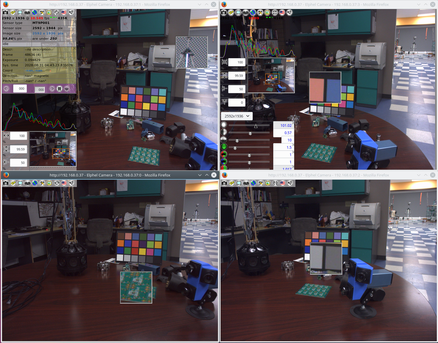
Fig 1. Four camvc instances for the four channels of NC393 camera
Users of earlier Elphel cameras can easily recognize familiar camvc web interface – Fig. 1 shows a screenshot of the four instances of this interface controlling 4 sensors of NC393 camera in “H” configuration.
This web application tests multiple underlaying pieces of software in the camera: FPGA code, Linux kernel drivers that control the low level of the camera operation and are handling 8 interrupts from the imaging subsystem (NC353 camera processor had just one), PHP extension to interact with the drivers, image server, histograms visualization program, autoexposure and white balance daemons as well as multiple PHP scripts and Javascript code. Luckily, the higher the level, the less changes we needed in the code from the NC353 (in most cases just a single new parameter – sensor port had to be introduced), but the debugging process included going through all the levels of code – bug chasing could start from Javascript code, go to PHP code, then to PHP extension, to kernel driver, direct FPGA control from the Python code (bypassing drivers), simulating Verilog code with Cocotb. Then, when the problem was identified and the HDL code corrected (it usually required several more iterations with simulation), the top level programs were tested again with the new FPGA bitstream. And this is the time when the integration of all the development in the same Eclipse IDE is really paying off – easy code navigation, making changes to different language programs – and the software was rebuilding and transferring the results to the target system automatically.
Camera core software
NC393 camera software aims the same goals as the previous models – allow the full speed operation of the imagers while minimizing real-time requirements to the software on the two levels:
- kernel level (tolerate large delays when waiting for the interrupts to be served) and
- application level – allow even scripting languages to keep up with the hardware
Interrupt latency is usually not a problem what working with full frame multi-megapixel images, but the camera can operate a small window at high FPS too. Many operations with the sensor (like changing resolution or image size) require coordinated updating sensor internal registers (usually over I²C connection), changing parameters of the sensor-to-memory FPGA channel (with appropriate latency), parameters of the memory-to-compressor channel, and parameters of the compressor itself. Additionally the camera software should provide the modified image headers (reflecting the new window size) when the acquired image will be recorded or requested over the network.
Application software just needs to tell when (at what frame number) it needs the new window size and the kernel plus FPGA code will take care of the rest. Slow software should just tell in advance so the camera code and the sensor itself will have enough time to execute the request. Multiple parameters modifications designated for a specific frame will be applied almost simultaneously even if frame sync pulses where received from the sensor while application was sending the new data.
Image-derived data remains available long after the image is acquired
Similar things happen with the data received from the sensor – image itself and histograms (they are used for the automatic exposure adjustment and white balancing). Application does not need to to read them before the next frame data arrives – compressed images are kept in a large (64MB per port) ring buffer in the system memory – it can keep record of several seconds of images. Histograms (for up to 4 different windows inside the full image for each sensor port) are preserved for 15 frames after being acquired and transferred over DMA to the system memory. Subset of essential acquisition parameters and image metadata (needed for Exif output) are preserved for 2048 and 511 frames respectively.
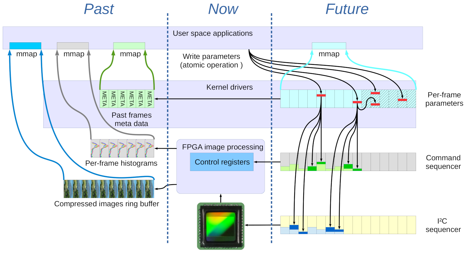
Fig 2. Interaction of the image sensor, FPGA, kernel drivers and user space applications
FPGA frame-based command sequencers
There are 2 sequencers for each of the four sensor ports on the FPGA level – they do not use any of the CPU resources:
- I²C sequencers handle relatively slow i2c commands to be sent to the senor, usually these commands need to arrive before start of the next frame,
- Command sequencers perform writes to the memory-mapped registers and so control the FPGA operation. These operations need to happen in guaranteed time just after the start of frame, before the corresponding subsystems begin to process the incoming image data.
Both are synchronized by the “start of frame” signals from the sensor, each sequencer has 16 frame pages, each page contains 64 command slots.
Sequencers allow absolute (modulo 16) frame address and relative (to current) frame address. Writing to the current frame (zero offset) is interpreted as “ASAP” and the commands are issued immediately, not synchronized by the start of frame. Additionally, if the commands were written too late and the frame sync arrived before they were executed, they will still be processed before the next frame slot page is activated.
Kernel support of the image frame parameters
There are many frame-related parameters that control image acquisition in the camera, including various sensor register settings, parameters that control gamma conversion, image format for recording to video memory (dedicated to FPGA DDR3 not shared with the CPU), compressor format, signal gains, color saturations, compression quality, coring parameters, histogram windows size and position. There is no such thing as the “current frame parameters” in the camera, at any given moment the sensor may be programmed for a certain image size, while its output data reflects the previous frame format, and the compressor is still not finished with even earlier image. That means that the camera should be aware of multiple sets of the same parameters, each applicable to a certain frame (identified by an absolute frame number). In that case the sensor “now” is receiving not the “current” frame parameters, but the frame parameters of a frame that will happen 2 frame intervals later.
Current implementation keeps parameters (all parameters are unsigned long) in a 16-element ring buffer, each element being a
|
908 909 910 911 912 913 914 915 916 |
/** Parameters block, maintained for each frame (0..15 in NC393) of each sensor channel */ struct framepars_t { unsigned long pars[927]; ///< parameter values (indexed by P_* constants) unsigned long functions; ///< each bit specifies function to be executed (triggered by some parameters change) unsigned long modsince[31]; ///< parameters modified after this frame - each bit corresponds to one element in in par[960] (bit 31 is not used) unsigned long modsince32; ///< parameters modified after this frame super index - non-zero elements in in mod[31] (bit 31 is not used) unsigned long mod[31]; ///< modified parameters - each bit corresponds to one element in in par[960] (bit 31 is not used) unsigned long mod32; ///< super index - non-zero elements in in mod[31] (bit 31 is not used) }; |
Interrupt driven processing of the parameters take CPU time (in contrast with the FPGA sequencers described before), so the processing should be efficient and not iterate through almost a thousand entries for each interrupt, It is also not practical to copy a full set of parameters from the previous frame. Parameters structure for each frame include mod[31] array where each element stores a bit field that describes modification of the 32 consecutive parameters, and a single mod32 represents each mod as a single bit. So mod32 == 0 means that there were no changes (as is true for the majority of frames) and there is nothing to do for the interrupt service routine. Additional fields modsince[31] and modsince32 mean that there were changes to the parameter after this frame. It is used to initialize a new (15 frames ahead of “now”) frame entry in the ring buffer. The buffer is modulo 16, so parameters for [this_frame + 15] share the same memory address as [this_frame-1], and if the parameter is not “modified since” (as is true for the majority of parameters), nothing has to be done for it when advancing this_frame.
There is a configurable parameter that tells parameter processing at interrupts how far to look ahead in the future (Fig.2 shows frames that are too far in the future hatched). The function starts with the current frame and proceeds in the future (up to the specified limit) looking for modified, but not yet processed parameters. Processing of the modified parameters involves calling of up to 32 “generic”(sensor-agnostic) functions and up to 32 their sensor-specific variants. Each parameter that triggers some action if modified is assigned a bitmask of functions to schedule on change, and when the parameter is written to buffer, the functions field for the frame is OR-ed, so during the interrupt only this single field has to be considered.
Processing parameters in a frame scans all the bits in functions (in defined order, starting from the LSB, generic first), the functions involve verification and calculation of derivative values, writing data to the FPGA command and I²C sequencers (deep green and blue on Fig. 2 show the new added commands to the sequencers). Additionally some actions may schedule other parameters changes to be processed at later frame.
User space applications and the frame parameters
Application see frame parameters through the character device driver that supports write, mmap, and (overloaded) lseek.
- write operation allows to set a list of parameters and apply these changes to a particular frame as a single transaction
- mmap provides read access to all the frame parameters for up to 15 frames in the future, parameter defines are provided through the header files under kernel include/uapi, so applications (such as PHP extension) can access them by symbolic names.
- lseek is heavily overloaded, especially for positive offsets to SEEK_END – such commands initiate special actions in this driver, such as waiting for the specific frame. It is partially used instead of the ioctl command, because lseek is immediately supported in most languages while ioctl often requires special extensions.
Communicating image data to the user space
Similar to handling of the frame acquisition and processing parameters, that deals with the future and lets even slow applications to control the process being frame-accurate, other kernel drivers use the FPGA code features to give applications sufficient time to process acquired data before it is overwritten by the newer one. These drivers use similar character device interface with mmap for data access and lseek for control, some use write to send data to the driver.
- circbuf driver provides access to the compressed image data in any of the four 64MB ring buffers that contain compressed by the FPGA data (FPGA also provides the microsecond-accurate timestmap and the image size). Each image is 32-byte aligned, FPGA skips additional 32 bytes after each frame. Compressor interrupt service routine (located in sensor_common.c) fills this area with some of the image acquisition metadata.
- histograms driver handles the histograms for the acquired images. Histograms are calculated in the FPGA on the image-to-memory path and so are active even if compressor is stopped. There are 3 types of histogram data that may be needed by the applications, and only the first one (direct) is provided by the FPGA over DMA, two others (derivative) are calculated in the driver and cached, so application request for the same derivative histogram does not require re-calculation. Histograms are calculated for the pixels after gamma-conversion even if raw (2 bytes/pixel) data is recorded, so table indices are always in the range of 0 to 255.
- direct histograms are provided by the FPGA that maintains data for 16 consecutive (last acquired) frames, for each of the 4 color channels (2 separate green ones), for each of the sensor ports and sub-channels (when multiplexers are used). Each frame data contain 256*4=1024 of the unsigned long (32 bit) values.
- cumulative histograms contain the corresponding cumulative values, each element equals to sum of the direct histogram values from 0 to the specified index. When divided by the value at index 255 (total number of pixel of this color channel =1/4 of all pixels in WOI) the result will tell what part of all pixels have values less or equal to the current.
- percentiles are reversed cumulative histograms, they tell what is the pixel level for which a certain fraction of all pixels has a value of equal or below it. These values refer to non-linear (gamma-converted) pixel values, so automatic exposure also uses reversed gamma tables and does interpolation between the two values in the percentile table.
- jpeghead driver generates JPEG/JP4 headers that need to be concatenated with the compressed output from circbuf (and with the end-of-image 0xff/0xd9 marker) to make a complete image file
- exif driver manipulates Exif data in the camera – it stores Exif frame-variable data for the last acquired frames in a 512-element ring buffer, allows to specify and set additional Exif fields, provides mmap read access to the metadata.
Camera applications
Current applications include
- Elphel PHP extension allows multiple PHP scripts to work in the camera, providing server-side of the web applications functionality, such as camvc.
- imgsrv is a fast image server that bypasses camera web server and transfers images and metadata avoiding any copying of extra data – network controller sends data over DMA from the same buffer where FPGA delivered compressed data (also over DMA). Each sensor port has a corresponding instance of imgsrv, serving different network ports.
- camogm allows simultaneous recording image data from multiple channels at up to 220 MB/s
- autoexposure is an auto exposure and white balance daemon that uses image histograms for the specified WOI to adjust exposure time, sensor analog gains and signal gain coefficients in the FPGA.
- pnghist is a CGI program that visualizes histograms as PNG images, it supports several histogram presentation modes.
Other applications that were available in the earlier NC353 series cameras (such as RTP/RTSP video streamer) will be ported shortly.
Future plans
NC393 camera has 12 times higher performance than the earlier NC353 series, and porting of the functionality of the NC353 is much more than just tweaking of the FPGA code and the drivers – large portions had to be redesigned completely. Camera FPGA project includes provisions for advanced image processing, and that changed the foundation of the camera code. That said, it is much more exciting to move forward and implement functionality that did not exist before, but we had to finish that “boring” part first. And as now it is coming closer, I would like to share our future development plans and invite others who may be interested to cooperate.
New sensors
NC393 was designed to have maximal flexibility in the sensor interface – this we learned from our experience with 303-313-333-353 series of cameras. So far NC393 is tested with one parallel interface sensor and one with a 4-lane HiSPI interface (both have links to the circuit diagrams). Each port can use 8 lanes+clock (9 differential) pairs and several more control/clock signals. Larger/faster sensors may use multiple sensors ports and so multiply available interface lines.
It will be interesting to try high sensitivity large pixel E2V sensors and ToF technology. TI OPT8241 seems to be a good fit for NC393, but OPT8241 I²C register map is not provided.
Quadcopters flying Star Wars style
Most quadcopters use brushless DC motors (BLDC) that maybe tricky to control. Integrated motor controllers that detect rotor position using the voltage on the power coils or external sensors (and so emulate ancient physical brushes) work fine when you apply only moderate variations to the rotation speed but may fail if you need to change the output fast and in precisely calculated manner. FPGA can handle such calculations better and leave CPU resources for the high level tasks. I would imagine such motor control to include some tiny FPGA paired with the high-current MOSFET drivers attached to the motors. Then use lightweight SATA cables (such as 3m 5602 series) to connect them to the NC393 daughter board. NC393 already has dual ARM CPU so it can use existing free software to fly drones and take video/images at the same time. Making it not just fly, but do “tricks” will be really exciting.
Image processing and High Level Synthesis (HLS) alternative
NC393 FPGA design started around a 16-channel memory access optimized for 2d data. Common memory may be not the most modern approach to parallel processing, but when the bulk memory (0.5GB of the DDR3) is a single device, it has to be shared between the channels and not all the module connection can be converted to simple stream protocols. Even before we started to add image processing, we have to maintain two separate bitstreams – one for the parallel sensors, and the other – for HiSPI (serial) ones. They can not be made run-time programmable as even the voltage levels are different, to say nothing that both interfaces together will not fit into Zynq FPGA – we already balancing around 80% of the slice utilization. Theoretically NC393 can use two of the parallel and 2 serial sensors (two pairs of sensor ports use two separate I/O banks with individually programmable supply voltage), but that adds even more variants to the top level module configuration and matching constraints files, and makes the code less readable.
Things will get even more complicated when there will be more active memory channels involved in the processing, especially when the inter-synchronization of the different modules processing multi-sensor 2d data is more complex than just stream in/stream out.
When processing muti-view scenes we will start with de-warping followed by FFT to implement correlation between the 4 simultaneous images and so significantly reduce ambiguity of a stereo-pair correlation. In parallel with working on Verilog code for the new modules I plan to try to reduce the complexity of the inter-module connections, making it more flexible and easier to maintain. I would love to use something higher level, but unfortunately there is nothing for me to embrace and use.
Why I do not believe in HLS
Focusing on the algorithmic level and leaving RTL implementation to the software is definitely a good idea, but the task is much more ambitious than to try to replace GCC or GNU/Linux operating system that even most proprietary and encryption-loving companies have to use. The gap between the algorithms and RTL code is wider than between the C code and the Assembler for the CPU, regardless of some nice demos with the Sobel filter applied to the live video stream or similar simple processing.
One of the major handicaps of the existing approach is an obsession with making modern reprogrammable FPGA code mimic the fixed-function hardware integrated circuits popular in the last century. To be software-like is much more powerful than to look like some old hardware. It is sure that separation of the application levels, use of the standard APIs are important, but it is most beneficial in the mature areas. In the new ones I consider it to be a beauty of coding to be able to freely cross any implementation levels, break some good programming practices, adjust it here and there, redesign and start over, balance overall performance and structure to create something new. Features and interfaces freeze will come later.
So what to use instead?
I do not yet know what it should be exactly, but I would borrow Python decorators and functionality of Verilog generate operators. Instead of just instantiating “black boxes” with rigid interfaces – allow the wrapper code (both automatically generated and hand-crafted) to get inside the instantiated modules code and modify it for the particular instances. “Decoration” meaning generation of the modified module code for the specific instances. Something like programmatic parametrization (modifying code, not just the parameter values, even those that direct generate operators).
Elphel FPGA code is source code based, there are zero of the “black boxes” in the design. And as all the code (109579 lines of it) is available it is accessible for the software too, and “robots” can analyze it and make it easier to manage. We would like to have them as “helpers” not as “wizards” who can offer just a few choices among the pre-programmed options.
To some extend we already do have such “helpers” – our current Python code “understands” Verilog parameter definitions in the source code, including some calculations of the derivative ones. That makes it possible for the Python programs running in the camera to use the same register addresses and bit fields as defined for the FPGA code implemented in the current bitstream.
When the cameras became capable of running FPGA code controlled by the Python program and we were ready to develop kernel drivers, we added extra functionality to the existing Python code. Now it is able not just to read Verilog parameters for itself, but also to generate C code to facilitate drivers development. This converter is not a compiler-like program that takes Verilog input and generates C header files. It is still a human-coded program that retrieves the parameters values from the Verilog code and helps developer by using familiar content-assist functionality of the IDE, detects and flags misspelled parameter names in PyDev (Eclipse IDE plugin for Python), re-generates output when the Verilog source is modified.
We also used Python to generate Verilog code for AHCI implementation, it seemed more convenient than native Verilog generate. Wrapping Verilog in Python and generating clean (for human analysis) Verilog code that can be used in wave viewer and in implementation tools timing analysis. It will be quite natural to make the Python programs understand more of Verilog code and help us manage the structure, generate matching constraints files that FPGA implementation tools require in addition to the HDL code. FPGA professionals probably use TCL scripts for that, it may be a nice language but I never used it outside of the FPGA scripting, so it is always a problem for me to recall how to use it when coming back to FPGA coding after long interruptions.
I did look at MyHDL of course, but it is not exactly what I need. MyHDL tries to replace Verilog completely and the structural modeling part of it suffers from the focus on RTL. I just want Python to help me with Verilog code, not to replace it (similar to how I do not think that Verilog is the best language to simulate CPU activities). I love Cocotb more – even its gentle name (COroutine based COsimulation) tells me that it is not “instead of” but “in addition to”. Cocotb does not have a ready solution for this project either (it was never a goal of this program) so here is an interesting project to implement.
There are several specific cases that I would like to be handled by the implementation.
- add new functionally horizontal connections in a clean way between hierarchical objects: add outputs all the way up to the common parent module, wires at the top, and then inputs all the way down to the destination. Of course it is usually better to avoid such extra connections, but their traces in module ports help to keep them under control. Such connections may be just temporary and later removed, or be a start of adding new functionality to the involved modules.
- generate a low footprint debug network to selected hierarchical modules and generate target Python code to probe/modify registers through this network accessing data by the HDL hierarchical names.
- control the destiny of the decorators – either keep them as separate pieces of code or merge with the original source and make the result HDL code a new “co-designed” source.
And this is what I plan to start with (in parallel to adding new Verilog code). Try to combine existing pieces of the solution and make it a complete one.
Leave a Reply