December 22, 2016
by Mikhail Karpenko
Sometimes we need to test disks connected to camera and find out if a particular model is a good candidate for in-camera stream recording application. Such disks should not only be fast enough in terms of write speed, but they should have short ‘response time’ to write commands. This ‘response time’ is basically the time between command sent to disk and a response from disk that this command has finished. The time between the two events is related to total write speed, but it can vary due to processes going on in internal disk controller.
The fluctuations in disk response time can be an important parameter for high bandwidth streaming applications in embedded systems as this value allows to estimate the data buffer size needed during recording, but this may be not very critical parameter for typical PC applications as modern computers are equipped with large amount of RAM. We have not found any suitable parameter in disk specifications we had which would give us a hint for the buffer size estimation and developed a small test program for this purpose.
(more…)
December 17, 2016
by Andrey Filippov
As we finished with the basic camera functionality and tested the first Eyesis4π built with the new 10393 system boards (it is smaller, requires less power and, is faster) we are moving forward with the in-camera image processing. We plan to combine our current camera calibration methods that require off-line post processing and the real-time image correction using the camera own FPGA resources. This project development will require switching between the actual FPGA coding and the software implementation of the same algorithms before going to the next step – software is still easier to design. The first part was in FPGA realm – it was to implement the fundamental image processing block that we already know we’ll be using and see how much of the resources it needs.
DCT type IV as a building block for in-camera image processing
We consider a small (8×8 pixel) DCT-IV to be a universal block for conditioning of the raw acquired images. Such operations as lens optical aberrations correction, color conversion (de-mosaic) in the presence of the lateral chromatic aberration, image rectification (de-warping) are easier to perform in the frequency domain using convolution-multiplication property and other algorithms.
In post-processing we use DFT (Discrete Fourier Transform) over rather large (64×64 to 512×512) tiles, but that would be too much for the in-camera processing. First is the tile size – for good lenses we do not need that large convolution kernels. Additionally we plan to combine several processing steps into one (based on our off-line post-processing experience) and so we do not need to sub-sample images – in our current software we double resolution of the raw images at the beginning and scale back the final result to reduce image degradation caused by re-sampling.
The second area where we plan to reduce computations is the replacement of the DFT with the DCT that is designed to be fed with the pure real data and so requires less arithmetic operations than DFT that processes complex input values.
Why “type IV” of the DCT?
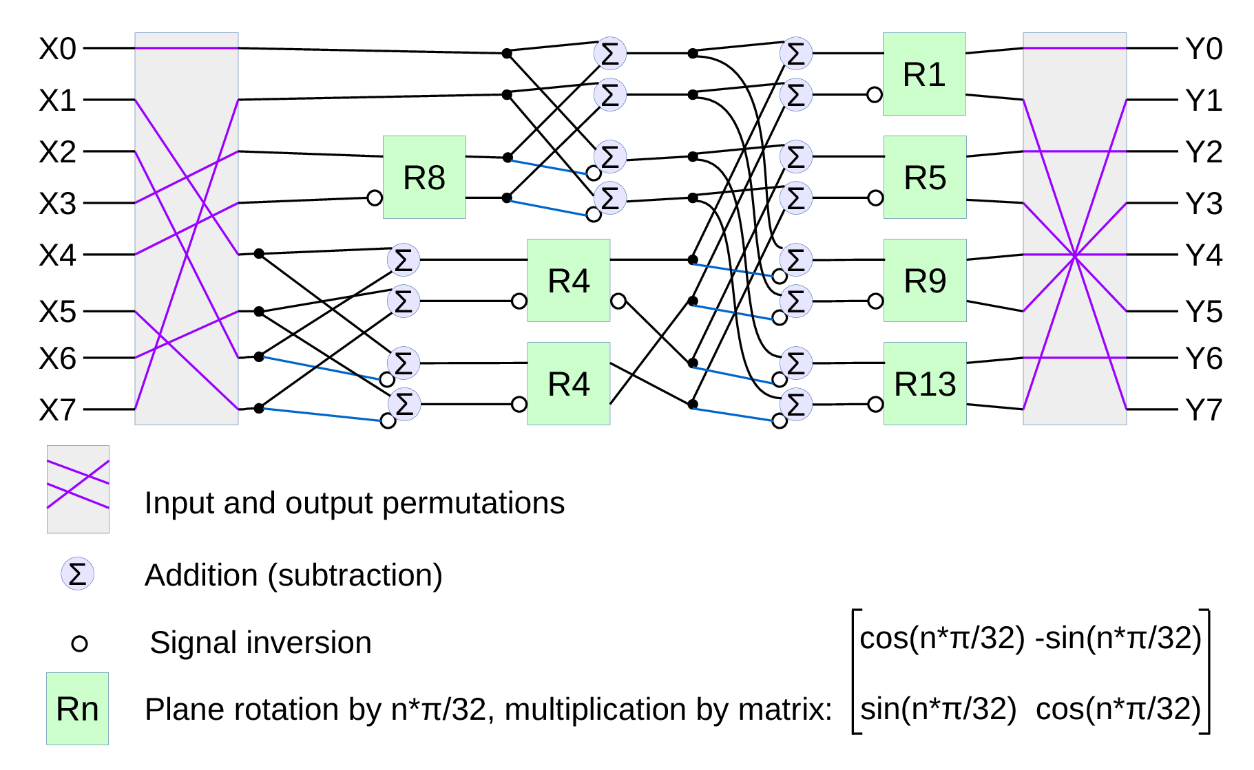
Fig.1. Signal flow graph for DCT-IV
We already have DCT type II implemented for the JPEG/JP4 compression, and we still needed another one. Type IV is used in audio compression because it can be converted to a modified discrete cosine transform (MDCT) – a procedure when multiple overlapped windows are processed one at a time and the results are seamlessly combined without any block artifacts that are familiar for the JPEG with low settings of the compression quality. We too need lapped transform to process large images with relatively small (much smaller than the image itself) convolution kernels, and DCT-IV is a perfect fit. 8-point DCT-IV allows to implement transformation of 16-point segments with 8-point overlap in a reversible manner – the inverse transformation of 8-point data may be converted to 16-point overlapping segments, and being added together these segments result in the original data.
(more…)
October 24, 2016
by Oleg Dzhimiev
Operation modes in conventional CMOS image sensors with the electronic rolling shutter
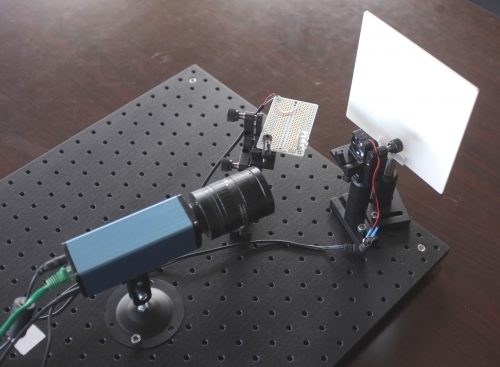
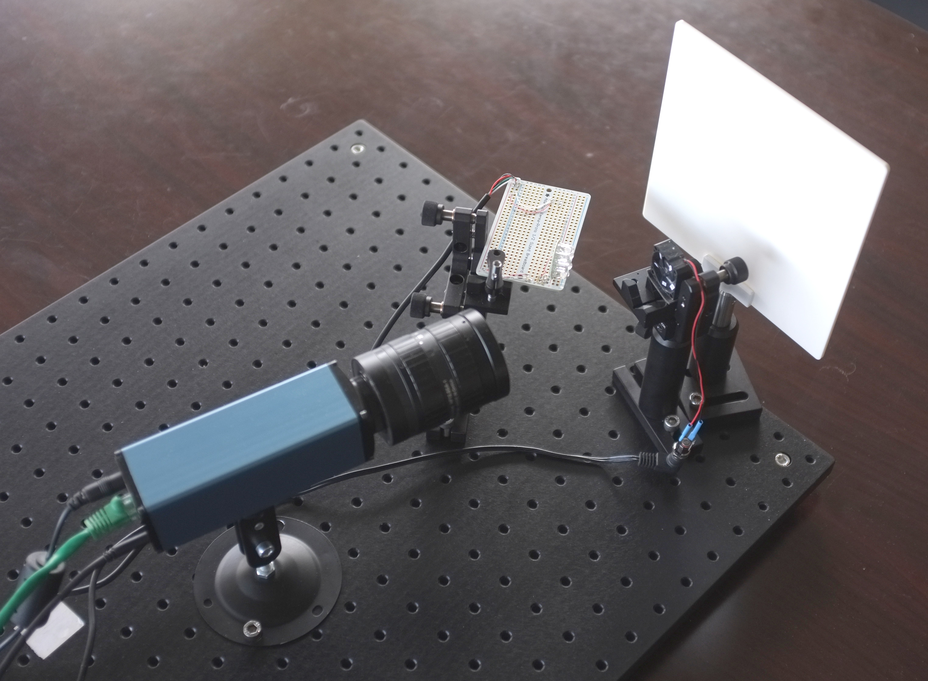
Flash test setup
Most of the CMOS image sensors have Electronic Rolling Shutter – the images are acquired by scanning line by line. Their strengths and weaknesses are well known and extremely wide usage made the technology somewhat perfect – Andrey might have already said this somewhere before.
There are CMOS sensors with a Global Shutter BUT (if we take the same optical formats):
- because of more elements per pixel – they have lower full well capacity and quantum efficiency
- because analog memory is used – they have higher dark current and higher shutter ratio
Some links:
So, the typical sensor with ERS may support 3 modes of operation:
- Electronic Rolling Shutter (ERS) Continuous
- Electronic Rolling Shutter (ERS) Snapshot
- Global Reset Release (GRR) Snapshot
GRR Snapshot was available in the 10353 cameras but ourselves we never tried it – one should have write directly to the sensor’s register to turn it on. But now it is tested and working in 10393s available through the TRIG (0x14) parameter.
(more…)
October 2, 2016
by Olga Filippova
On October 8th, 2016 Andrey will be presenting his work on VDT – Free Software Environment for FPGA Development at an open source digital design conference, ORCONF 2016. ORCONF 2016
The conference will take place in Bologna, Italy, and we are glad for the possibility to meet some of European users of Elphel cameras, and to connect with the community of developers excited about open source design, free software and open hardware.
Elphel will be present at the conference by Andrey Filippov from USA headquarters and Alexadre Poltorak, founder of Swiss 3D4Pi mobile mapping company, working closely with Elphel to integrate Eyesis4Pi, stereophotogrammetric camera, for the purpose of image based 3D reconstruction applications. Andrey will bring and demonstrate the new multisensor NC393 H-camera and Alexandre plans to take some panoramic footage with Eyesis4Pi camera, while in Bologna.
September 19, 2016
by Andrey Filippov
Since we started to deliver first NC393 series cameras in May we were working on the cameras software – original version was rather limited. While it was capable of serving images/video over the network and recording them on the internal m.2 SSD, it did not have the advanced image acquisition control (through the GUI and programmatically) that was standard for the earlier NC353 series. Now the core functionality is operational and in a month we plan to have the remaining parts (inter-camera synchronization, working with multiple sensors per-port with 10359 multiplexer, GPS+IMU logging) online too. FPGA code is already ported, but it needs to be tested and a fair amount of troubleshooting, identifying the problems and weeding out the bugs is still left to be done.
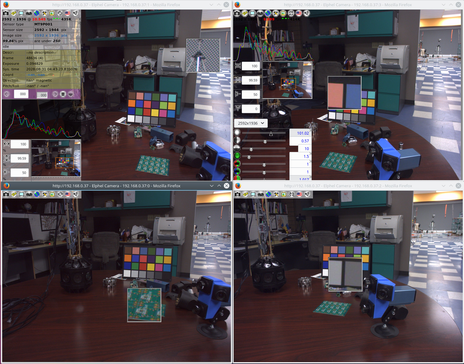
Fig 1. Four camvc instances for the four channels of NC393 camera
Users of earlier Elphel cameras can easily recognize familiar camvc web interface – Fig. 1 shows a screenshot of the four instances of this interface controlling 4 sensors of NC393 camera in “H” configuration.
(more…)
September 13, 2016
by Mikhail Karpenko
Introduction
Elphel cameras use camogm, a user space application, for recording acquired images to a disk storage. The application is developed to use such storage devices as disk drives or USB drives mounted in the operating system. The Elphel393 model cameras have SATA-2 controller implemented in FPGA, a system driver for this controller, and they can be equipped with an SSD drive. We were interested in performing write speed tests using the SATA controller and a couple of M.2 SSDs to find out the top disk bandwidth camogm can use during image recording. Our initial approach was to try a commonly accepted method of using hdparm and dd system utilities. The first disk was SanDisk SD8SMAT128G1122. According to the manufacturer specification [pdf], this is a low power disk for embedded applications and this disk can show 182 MB/s sequential write speed in SATA-3 mode. We had the following:
|
|
~# hdparm -t /dev/sda2 /dev/sda2: Timing buffered disk reads: 274 MB in 3.02 seconds = 90.70 MB/sec ~# time sh -c "dd if=/dev/zero of=/dev/sda2 bs=500M count=1 && sync" 1+0 records in 1+0 records out real 0m6.096s user 0m0.000s sys 0m5.860s |
which results in total write speed around 82 MB/s.
(more…)
September 8, 2016
by Oleg Dzhimiev
Along with the documentation there is a number of articles explaining the dynamic debug (dyndbg) feature of the Linux kernel like this one or this. Though we haven’t found anything that would extend the basic functionality – so, we created a web interface using JavaScript and PHP on top of the dyndbg.
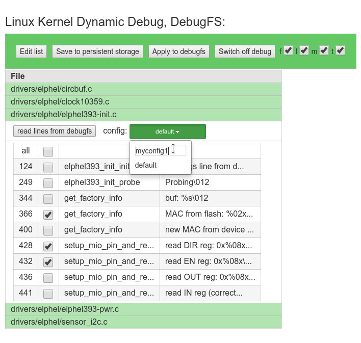
Fig.1 debugfs-webgui
(more…)
July 11, 2016
by Andrey Filippov
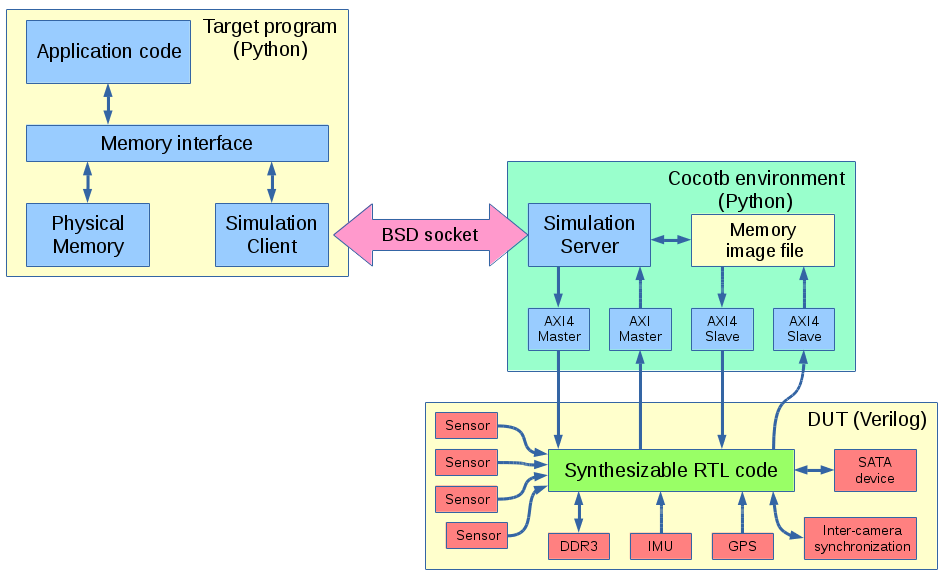
Or at least larger (verification) part of it – interfaces, packages and a few other synthesizable features are very useful to reduce size of Verilog code and make it easier to maintain. We now are able to run production target system Python code with Cocotb simulation over BSD sockets.
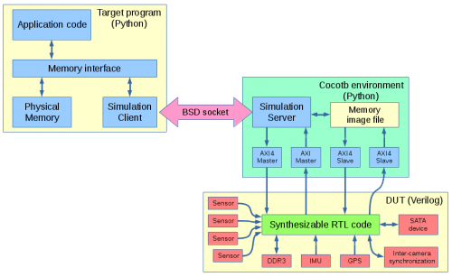
Client-server simulation of NC393 with Cocotb
Previous workflow
Before switching to Cocotb our FPGA-related workflow involved:
- Creating RTL design code
- Writing Verilog tests
- Running simulations
- Synthesizing and creating bitfile
- Re-writing test code to run on the target system in Python
- Developing kernel drivers to support the FPGA functionality
- Developing applications that access FPGA functionality through the kernel drivers
Of course the steps are not that linear, there are hundreds of loops between steps 1 and 3 (editing RTL source after finding errors at step 3), almost as many from 5 to 1 (when the problems reveal themselves during hardware testing) but few are noticed only at step 6 or 7. Steps 2, 5, 6+7 involve a gross violation of DRY principle, especially the first two. The last steps sufficiently differ from step 5 as their purpose is different – while Python tests are made to reveal the potential problems including infrequent conditions, drivers only use a subset of functionality and try to “hide” problems – perform recovering actions to maintain operation of the device after abnormal condition occurs.
(more…)
May 22, 2016
by Andrey Filippov
Elphel cameras offer unique capabilities – they are high performance systems out of the box and have all the firmware and FPGA code distributed under GNU General Public Licenses making it possible for users to modify any part of the code. The project does not use any “black boxes” or encrypted modules, so it is simulated with the free software tools and user has access to every net in the design. We are trying to do our best to make this ‘hackability’ not just a theoretical possibility, but a practical one.
Current camera FPGA project contains over 400 files under version control and almost 100K lines of HDL (Verilog) code, there are also constraints files, tool configurations, so we need to provide means for convenient navigation and modification of the project by the users.
We are starting a series of tutorials to facilitate acquaintance with this project, and here is the first one that shows how to install and configure the software. This tutorial is made with a fresh Kubuntu 16.04 LTS distribution installed on a virtual machine – this flavor of GNU/Linux we use ourselves and so it is easier for us to help others in the case of problems, but it should be also easy to install it on other GNU/Linux systems.
Later we plan to show how to navigate code and view/modify tool parameters with VDT plugin, run simulation and implementation tools. Next will be a “Hello world” module added to the camera code base, then some simple module that accesses the video memory.
Video resolution is 1600×900 pixels, so full screen view is recommended.
Download links for: video and captions.
Running this software does not require to have an actual camera, so it may help our potential users to evaluate software capabilities and see if it matches their requirements before purchasing an actual hardware. We will also be able to provide remote access to the cameras in our office for experimenting with them.
May 10, 2016
by Andrey Filippov
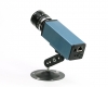
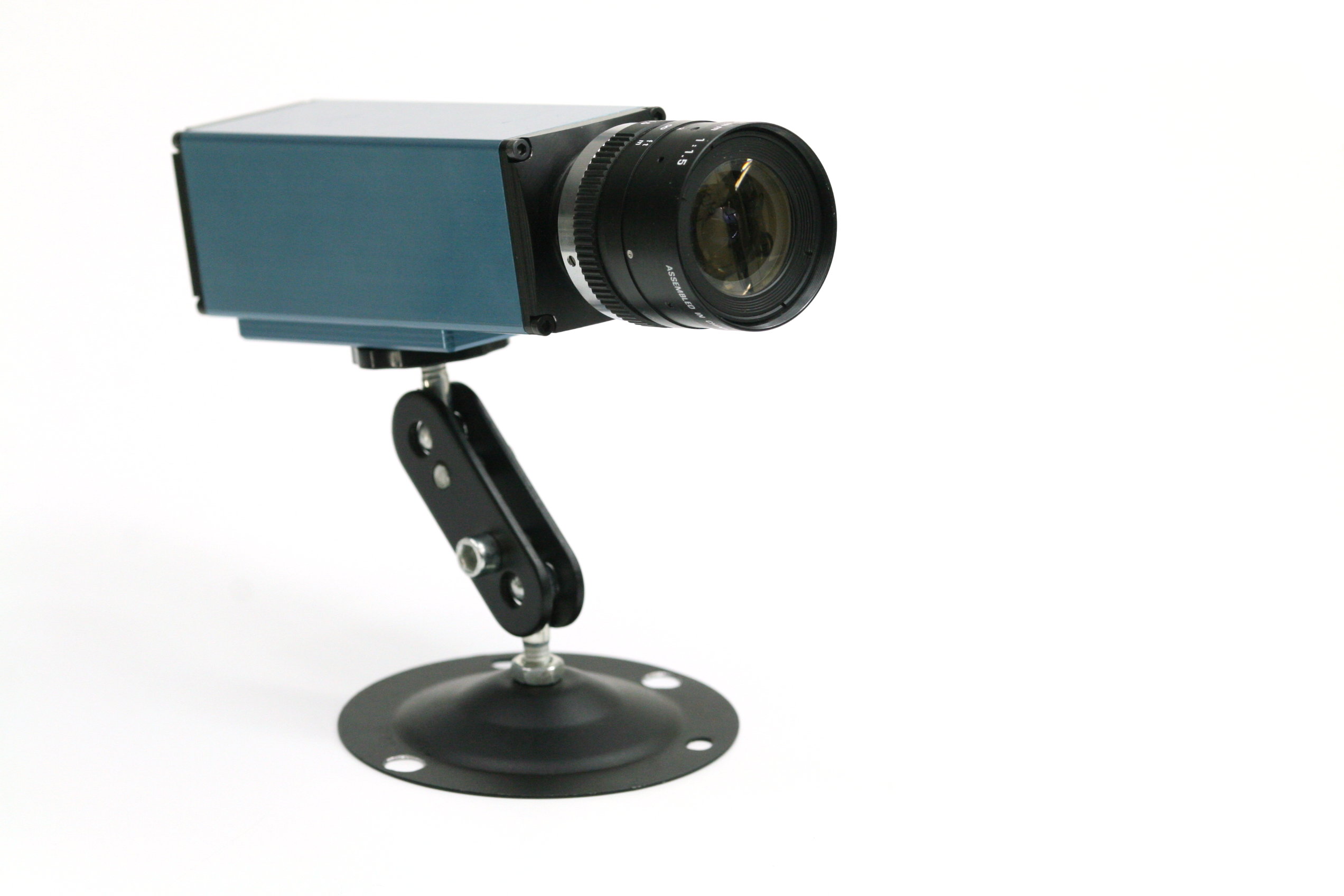
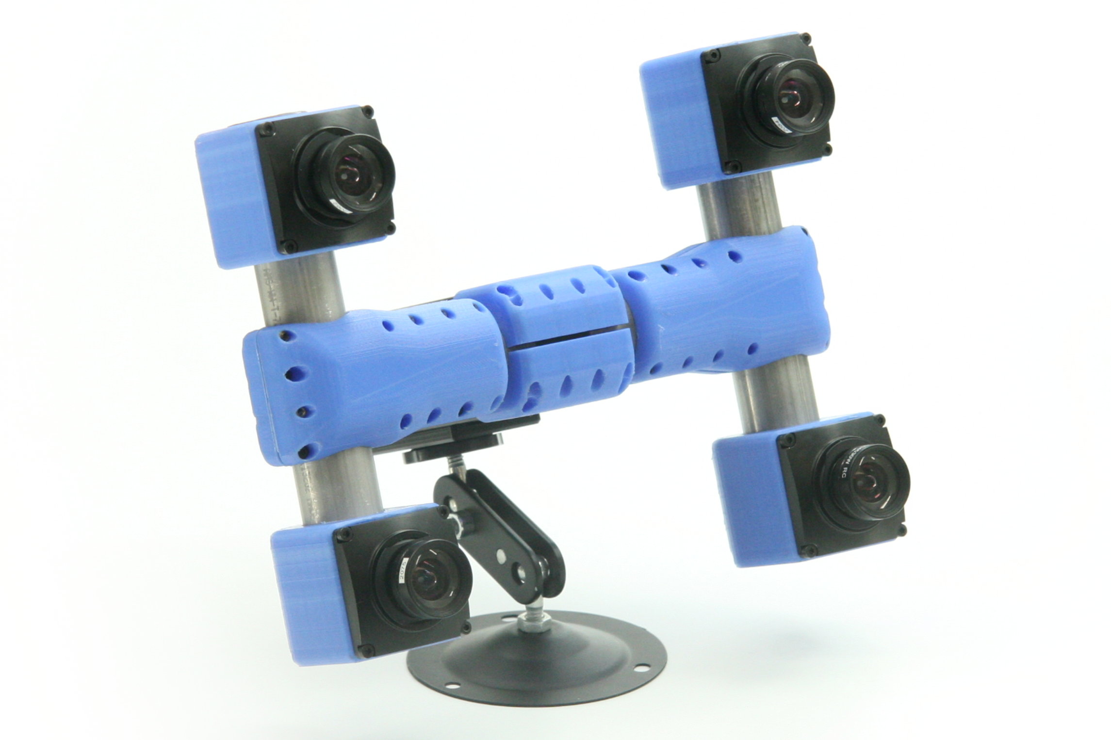
Two weeks ago we were making photos of our first production NC393 camera to post an announcement of the new product availability. We got all the mechanical parts and most of the electronic boards (14MPix version will be available shortly) and put them together. Nice looking camera, powered by a high performance SoC (dual ARM plus FPGA), packaged in a lightweight aluminum extrusion body, providing different options for various environments – indoors, outdoors, on board of the UAV or even in the open space with no air (cooling is important when you run most of the FPGA resources at full speed). Tons of potential possibilities, but the finished camera did not seem too exciting – there are so many similar looking devices available.

NC393 camera, back panel view. Includes DC power input (12-36V and 20-75V options), GigE, microSD card (bootable), microUSB(type B) connector for a system console with reset and boot source selection, USB/eSATA combo connector, microUSB(type A) and 2.5mm 4-contact barrel connector for external synchronization I/O
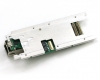
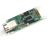
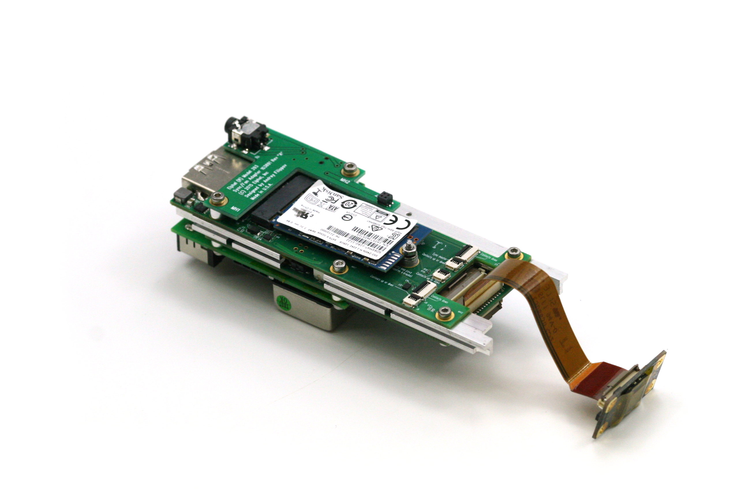
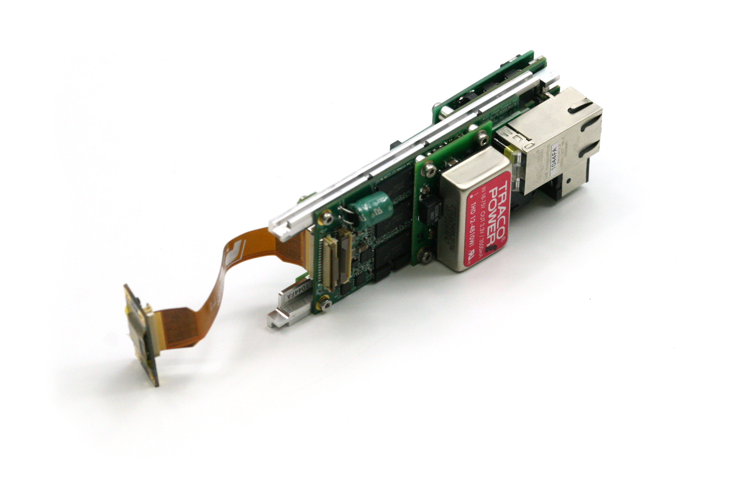
NC393 assembled boards: 10393(system board), 10385 (power supply board), 10389(interface board), 10338e (sensor board) and 103891 - synchronization adapter board, view from 10389. m.2 2242 SSD shown, bracket for the 2260 format provided. 10389 internal connectors include inter-camera synchronization and two of 3.3VDC+5.0VDC+I2C+USB ones.
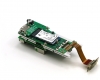
NC393 assembled boards: 10393(system board), 10385 (power supply board), 10389(interface board), 10338e (sensor board) and 103891 - synchronization adapter board, view from 10385
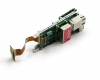
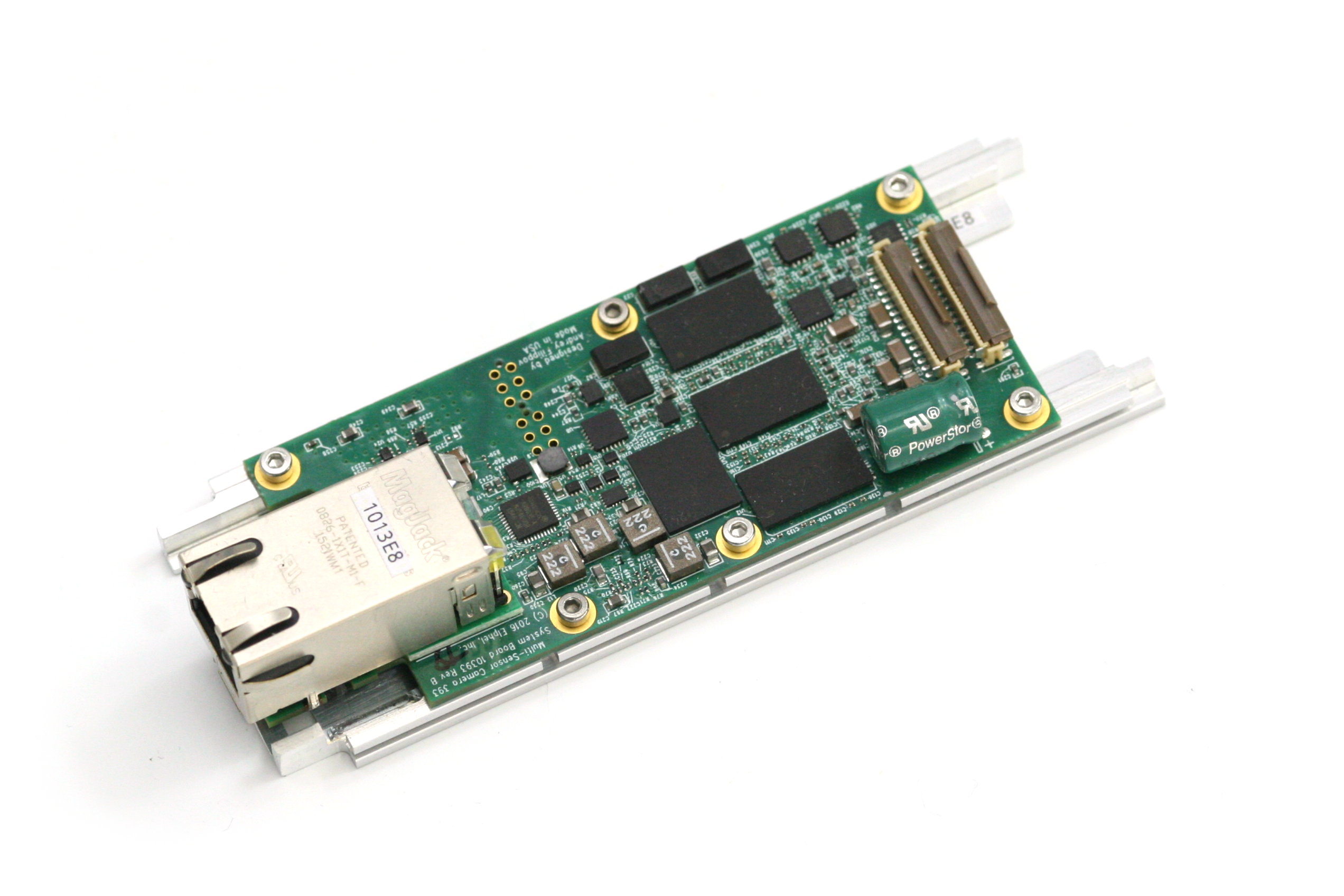
10393 system board attached to the heat frame, view from the heat frame. There is a large aluminum heat spreader attached to the other side of the frame with thermal conductive epoxy that provides heat transfer from the CPU without the use of any spring load. Other heat dissipating components use heat pads.
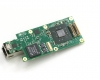
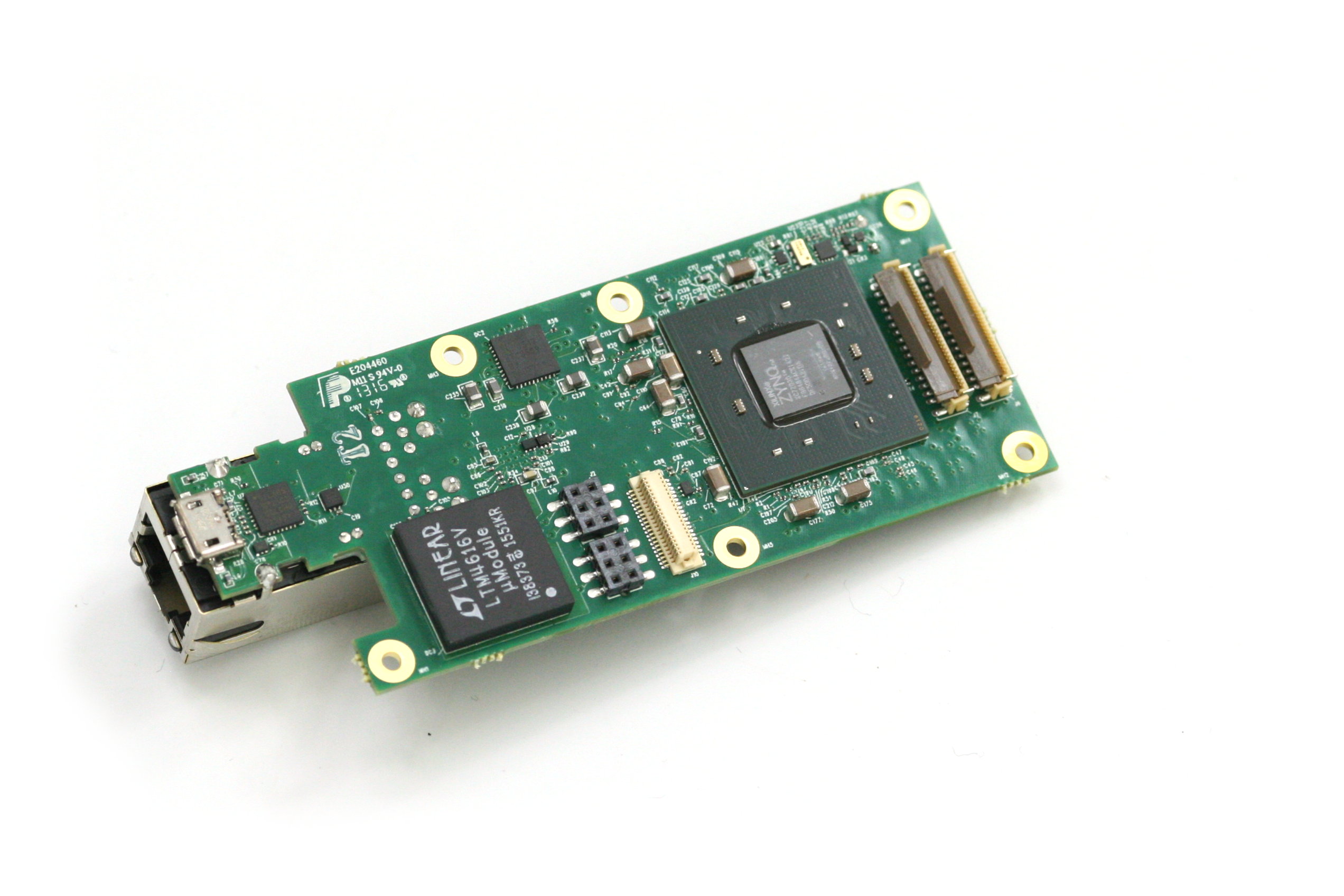
10393 system board attached to the heat frame, view from the 10393 board
10393 system board, view from the processor side
An obvious reason for our dissatisfaction is that the single-sensor camera uses just one of four available sensor ports. Of course it is possible to use more of the freed FPGA resources for a single image processing, but it is not what you can use out of the box. Many of our users buy camera components and arrange them in their custom setup themselves – that does not have a single-sensor limitation and it matches our goals – make it easy to develop a custom system, or sculpture the camera to meet your ideas as stated on our web site. We would like to open the cameras to those who do not have capabilities of advanced mechanical design and manufacturing or just want to try new camera ideas immediately after receiving the product.
(more…)
Next Page »


