Quadrotor copter with machine vision for contest
This page gives brief overview of multirotor UAV platform called “Tau”, which is built specially for participating in flying robots contest which is established by Russian Croc company. For now contest has only russian participants, probably because it was made for a first time.
Our team name was “Autonomous aerospace”. We are from Krasnoyarsk, 1M people city in Siberia. We had experience in UAV airplane development and manufacturing. We’ve grew up from student and postgraduate student university (SFU) scientific team to startup company.
Doing contest machine we were not looking for easiest way of implementation. Some of the purposes are: further developing of our autopilot and getting experience of integrating machine vision functionality in real-time into control loop.
During contest preparation we dealed for a first time with multyrotor platform . There was only airplanes autopiloting experience before. Adopting autopilot for quadrotor was not so obvious as we expected, but we succeded. Now proudly can say, that we built first quadrotor which calculates all the navigation and control math under QNX real-time operating system :). At least no one did any crazy stuff like this before 🙂
Mission
Mission is to take off from start marker, follow simple maze toward finish marker, touch down within its contour and than fly back. Then landing on start marker and cutoff engines. On path to target random barrier is set. It can be moved by organizators across the wall and gate might be aligned at left, at right or anywhere between walls.
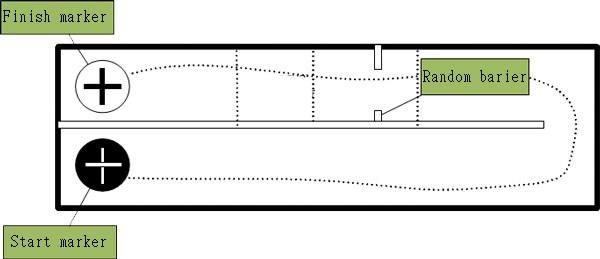
Drone is allowed to touch walls, but not allowed to touch the ground.
On-board UAV control system
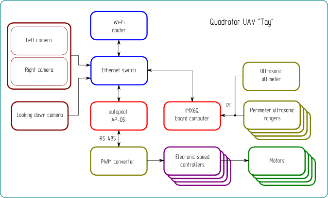
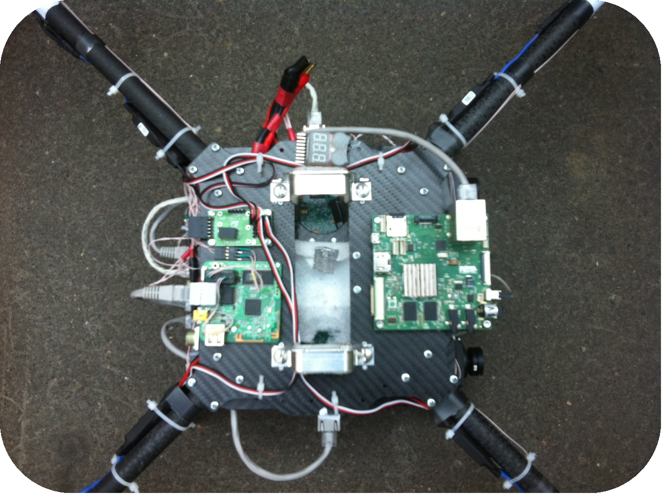
Computers
Central control unit is autopilot AP-05 (AP). It has embedded inertial navigational system (INS), air data system (ADS), global navigational satellite systems GLONASS/GPS (GNSS). Computer in AP-05 – is ARM9 family processor with 400MHz clock frequency and 64 megabytes of RAM. Operation of computer is conducted under QNX Neutrino real time operating system (RTOS) control. QNX is used under academic licence. Major point is implementation of navigational and control loop under QNX by separate processes: fnav for navigation, fcont for control. Loop frequency is 200 Hz.
Decicions for flight in contest maze is made in autopilot by setting input values for roll, pitch and yaw PID regulators.
Machine vision computer (MVC) is i.MX6Q SABRE lite board with 4 processors of Cortex-A9 archetecture. For the research of QNX technologies machine vision is also computed under QNX.
Connection between AP and MVC is made by Ethernet via native qnet protocol.
For the programmer is gives transparency and flexibility, all interprocess communication is unix-like locally or remotely by qnx messages. Local is conducted by kernel, remote by kernel+qnet.
Sensors
As a proximity sensors ultrasonic rangefinders SRF08 are used. They are mounded at bumper each for front, rear, left, right sides accordingly. Same sensor is used for altimetry. Sensors are connected to i.MX6Q SABRE lite (MVC) via I2C interface to the same bus with different adresses. Doing altitude and wall navigation control loop over such a long way looks weird. All because AP doesn’t have external I2C due to its noise vulnerability. Process which polls range finders reflects data to the system by /dev/fsrf resource manager. Autopilot reads this data over qnet stack like /net/mvc/dev/fsrf file. After reading by navigational process range data is filtered and after reflected as feedback for altitude control and wall avoidance algorithm.
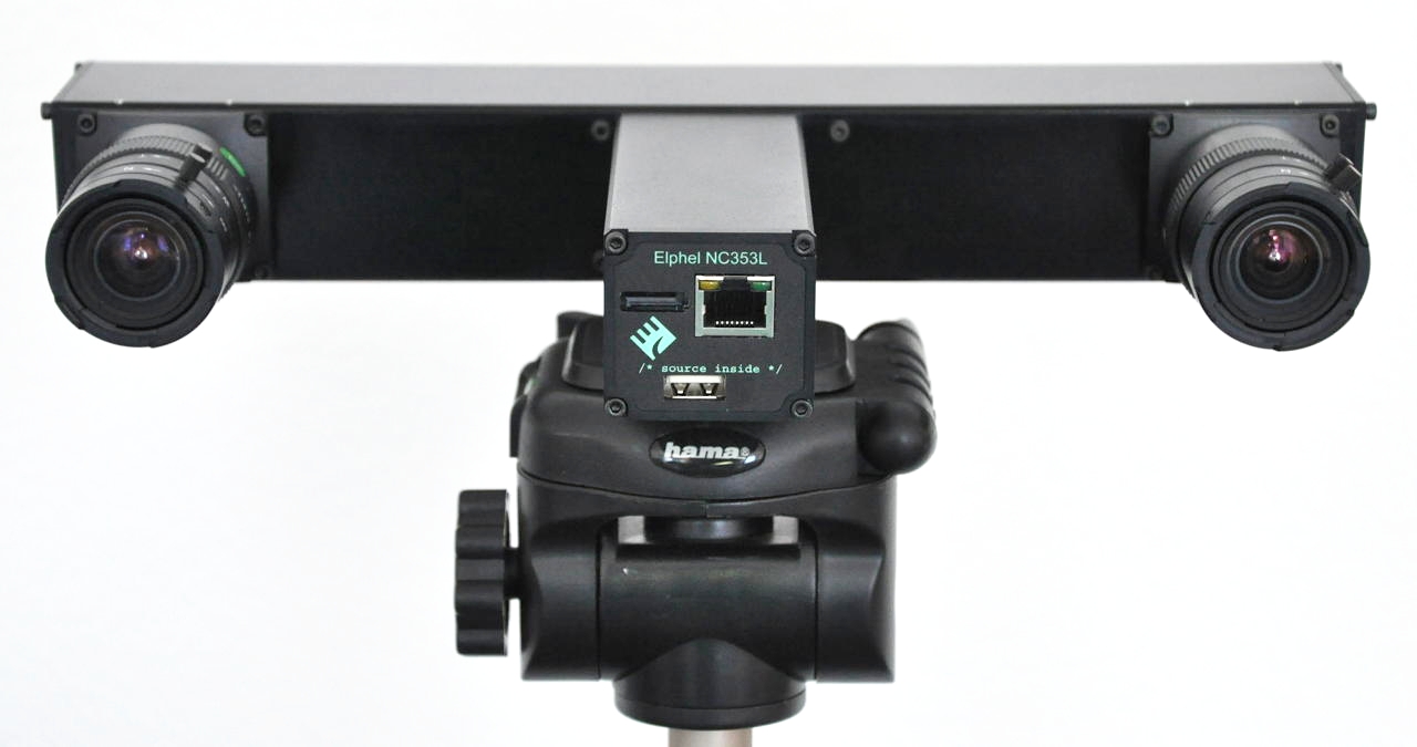
When we were looking for camera main problem was making an software interface for OpenCV in QNX. Making port of webcam USB interface to QNX in a short time seemed impossible, because of lack of knowledge in that field.
Thats why search for camera was narrowed only on IP cameras. Finally Elphel NC353L was found. It has several software interfaces for image: MJPEG over RSTP; HTTP. Camera has opened sources, so it seemed guaranteed way to make own low level protocol and image pre-processing.
Also camera has multiply configurational parameters for optimizing real time picture. Additionally matrix has higher resolution, than other cameras in same price segment.
With understanding that camera is open sourced we estimated our chances to miss appropriate solution as very low and this estimation was correct =).
Calculation of machine vision algorithm is conducted by process called fmv, and its discrete results is represented at /dev/fmv resource manager.
Machine vision
Start finish markers search
Searching for start/finish points is done by comparison of current image colour histograms with histograms of reference images. Histograms for B,R,G channels was compated accordingly, and then integral weighted estimation of similarity was calculated. Similarity is calculated separately for start and finish markers.
Stereo vision
For the barrier gate entrance we initially decided to implement stereo vision algorithms to determine its position. At the beginning of contest preparations width between walls on final approach to finish marker supposed to be 20 meters. It seemed challenging to find gate with 3m width. Thats why we decided to integrate Elphel NC353L solution. This version has multiplexor board, which simultaniously gather both sensor data to single image. Stereo camera was generously provided us by Elphel company to participate in contest.
We had previously tested semi-global block matching algorithm (SGBM). Method gives disparity map from two images. Using SGBM method, requiers distortion remap and aligning preprocessing of input images. Using matrices of internal parameters of cameras we performed images rectification, so left image row coincides with rows of right image. Experimentally we tuned scene parameters and looked for optimal diversity map. Diversity map has same dimentions as input images, but consist of 16 bit depth values. Seeing on single row in the middle of image, selected by INS to fit horizon we recoverd distance to near objects and supposed to determine gate.
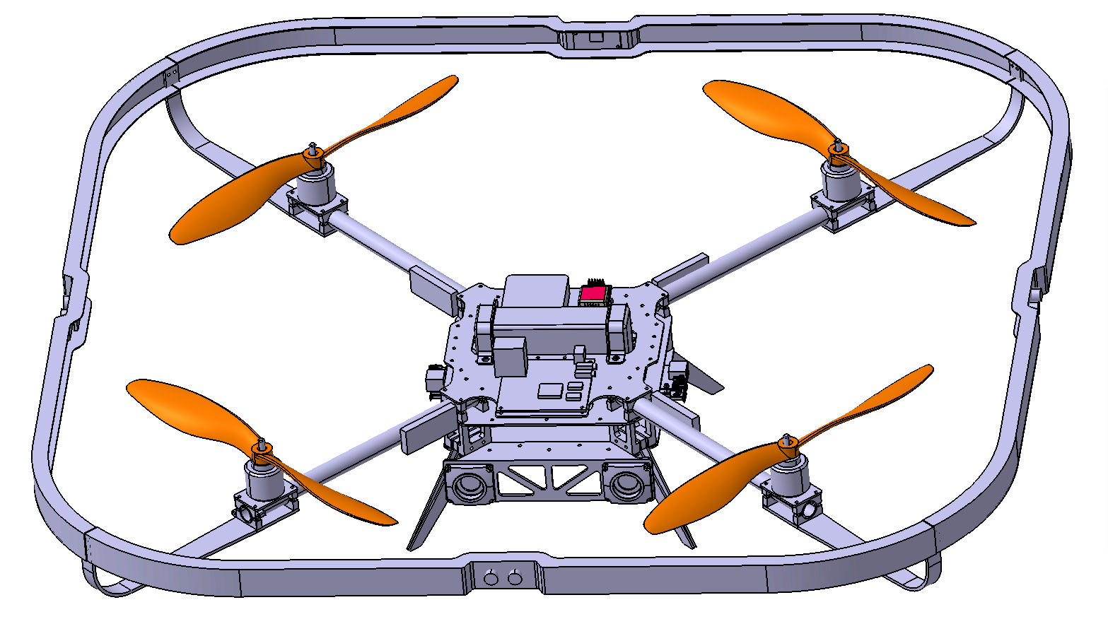
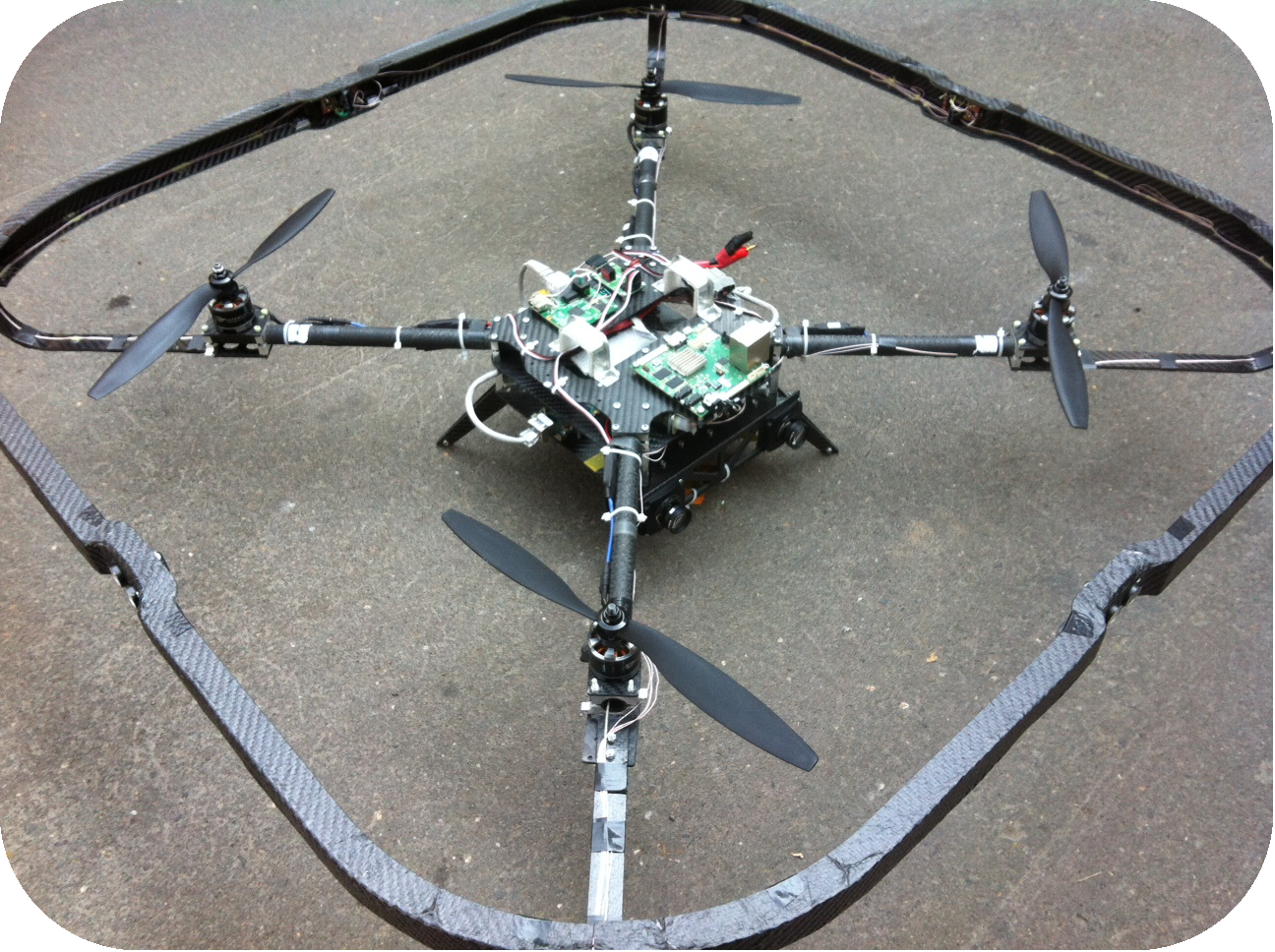
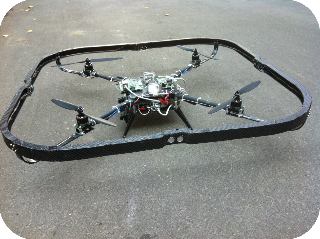
Multicopter UAV Tau frame design
Starting from the design…
| For compact setting of all required devices we decided to make central frame with 3 levels. Each level is milled carbon fiber plate. | 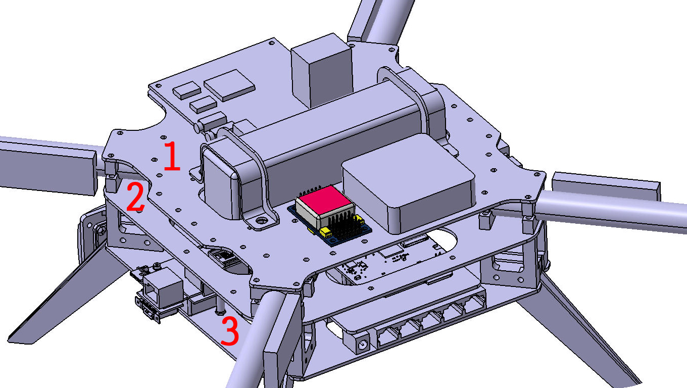 |
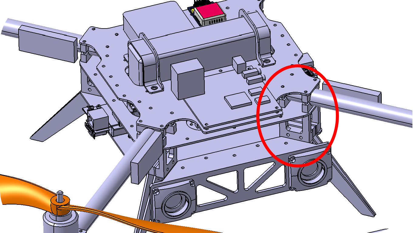 |
Level plates are fitted together by aluminium spacers. Between first and second levels there are carbon beams that are tighten between aluminium clamps. |
| At the end of each beam motor is mounted using aluminium brackets. Motors are working with 12″ x 4.5 propellers. | 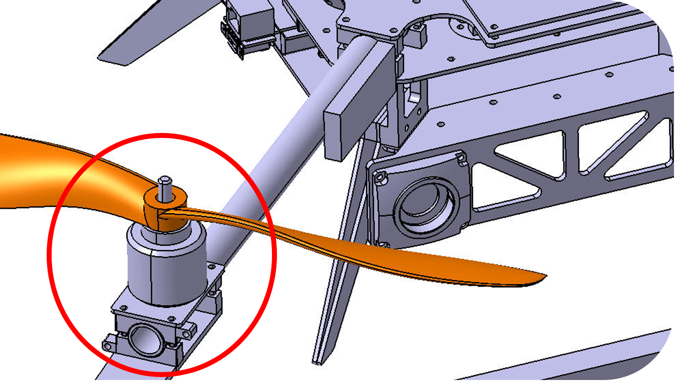 |
|
For the protection of propellers and equipment special bumper was made. 4 parts form closed perimeter. Bumper part has U-like cut and made of carbon 3 layer composite sandwich. Mounding of bumper is made by Г-like bracket, which is fixed at bottom of motor mount. |
| After design process production and assembly started. Fristly carbon fiber plates and beams were baked. Parallely all aluminium parts were milled. On preparated plates we milled them on CNC. Then molds for bumper and brackets were milled. | 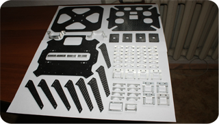 |
After all assembly started!
In a five days we fit everything together and made wiring of all devices.
Design of airframe in STEP format is freely avaiable: with all equipment and as plain frame.
 |
 |
 |
Flight testing
When everything were done on assembly 10 days before contest begin left. Actually we had flight test platform before, so we started not from scratch in a flight software.
Previous results were got on fiber glass strong frame before. Some explanations are made on russian in following videos:
After contest drone assembly we spend 5 days to make it flight properly: maintain attitude and regulate distance from the walls.
Next five days we spent to test all mission algorithm in a combination with machine vision and real markers. We’ve got some sucessful complete tests, but all system was very unstable. Most of the problems was about flying. A lot of time was eaten by i2c rangers problems: high current of motors and vibration were making contact and ground potential unstable, and it lead to bus stuck. When bus stuck, altimeter is also stucks, what was leading to engines turn off. Many thanks for our designers and all mechanical shop. In dozens of fallings we’ve once broke bumper braket, and one leg.
Algorithm for maze flying is classical, keep right, keep distance from the walls and pray :). We do not making turns, UAV maintains yaw, which is set on initial alignment. And it is aligned by rear side toward right direction at start. So it begins to fly backwards, than left, then front. And on a flight back – in reverse.
Fly front means to hold distance from front wall. When wall is far, front ranger is saturated in its maximum value, so regulator moves drone forward, by tilting its pitch front.
Contest video
In a real contest (sizes were officially corrected) distance between final approach walls became 5 meters, so finding gate was not a such big problem anymore. So barier detection was made in autopilot by finite state machine. If front stereo camera (by one of its eye) have seen ellipse in front of it, that means we have passed the gate and must see marker soon by looking down camers. If no, we probably holding right now distance from the barrier wall and must move left.
First attempt
It was failed because of improper finite state machine criterion for barrier avoidance. Drone thought that it has reached barier and next cycle it thought it has reached front wall at marker, didn’t find any markers and turned back.
Second attempt
Here we have our machine vision algorithm failed. Camera didn’t recognized landing marker, so drone tryed to find on the way back and it was dead end of algorithm.
As always there were just a question of two days of debugging to make everything right 🙂
Conclusion
We have not completely succeeded, but we have not failed.
Our team dramatically improved existed software and developed new direction – machine vision.
That was great teamwork experience, that charged our team to handle further challenges.
Update 30.10.2013:
During posting this text, new contest was announced for a 2014. We going to create new team of only students for doing new contest mission with already prepared machine. Now we have chance to get initial ideas realized.
[…] […]
I like your blog.I enjoyed reading your blog.It was amazing.Thanks a lot.