Elphel Eyesis camera optics and lens focus adjustment
Designing for low parallax
texture_tiles
When we started working on Eyesis project our first goal was to make the panoramic head as compact as possible to reduce parallax between sensors. That not only reduces the stitching artifacts but also decreases the minimal distance to object without dead zones between the individual camera.
 The first practical step was to reduce the PCB area around the sensors, especially in one direction, so multiple camera boards can be placed closer to each other, For that purpose we preserved the basic design of the proven 10338 sensor board, just changed the layout to make it more compact. The board 10338D is just 15mm wide – more than twice less than the older design.
Next step was to run mechanical CAD program and try to place the boards and lenses. Most of the Elphel cameras were designed for the C/CS-mount lenses, but when I tried to place them I immediately found out that when using 10 or 8 cameras around even the C-mount thread (CS is the same size but even closer) will be the limiting factor, not the sensor PCB that we already made smaller.
C-mount lenses won’t fit, what about the M12 ones?
At that time I was rather suspicious about the smaller M12 or “S-mount” or even “board” lenses – when I looked at them earlier most of them all were inexpensive low-power and low resolution ones. But hoping that advances in high resolution/small pixel size sensors increased demand for good quality lenses we decided to give them a try .
In order to cover 360 degrees horizontal with 8 cameras we needed each of them to cover 45 degrees (slightly more to provide overlap at shorter distances), with the sensors we use it corresponds to approximately 4.8 mm focal length. “Approximately” is because field of view is not completely defined by the focal length, among other things it is also related to lens geometric distortions.
Are lens distortions always bad?
For multi-sensor panoramic applications it is beneficial to have mild barrel distortion as ideal lens (with zero distortions) would have more pixels per angular degree near the edges than in the center. Barrel distortion provides more uniform angular resolution per pixel, additionally it’s field of view is opposite to the barrel, it is a cushion-like, so it is easier to provide overlap in the corners where reduced resolution is tolerable, but not the gaps. Contrary, lenses with cushion distortions have barrel-like field of view so to provide positive overlap in the corners more overlap around the “equator” will be needed (so effectively less pixels used in the most critical areas). In addition to the 5 identical targets you can see one twice larger – we used it for absolute distance calibration.
Camera was placed at just 2.25 meters from the targets. Of course it is much closer than the distance we need to focus camera (taking depth of field into account we need to focus cameras at approximately 10 meters, so everything form infinity down to 7 m will be in sharp. Having >45 degrees FOV it would be difficult to us to have such test, so we tried to do it differently. If we can compensate the tilt and then move sensor closer to the lens by 7 microns that would compensate for the object plane moving from 2.25m to 10 m
At this stage we decided to try several off-the-shelf lenses with approximately the same focal length and try to evaluate their resolution and distortion. We tried lenses from Sunex, Edmund Optics and Vision Dimension (VD) – and the last one showed the best results. None of them had barrel distortion, but VD had much lower cushion than the others. And it exhibited one of the best resolutions compared to the larger C-mount lenses we used before. Additionally it is a very “short” lens with small distance between the entrance pupil (point used when calculating the parallax) and the image plane, so we started our overall mechanical design based on that lens. With outdoor panoramic applications it is rather difficult to make lenses interchangeable because the protective windows have to be rather close to the lenses and so switch to the different lens size would require substantial mechanical redesign.
Challenges of fine focusing high power high resolution M12 lenses
M12 lens mount presents additional challenges. While larger C/CS mount have fixed flange distance and most of them have focus ring, simpler/smaller M12-mount lenses do not have focus ring and are focused by the mount thread itself. Of course, that method has much lower precision and even when using lock nuts is not as good as focusing of the C-mount lenses. It may be OK for the low power lenses (high F-number), but not adequate for the high-power (we used F=1.8) ones. Additionally small pixel size of the sensor puts a high limit of the F-number, for 2.2μm pixels diffraction reduces resolution above F number ~4.0-5.6. In addition to difficulty to focus the center of the image, usage of the mounting thread for focusing leads to orientation uncertainty, the lens optical axis might deviate from a perpendicular to the sensor.
… and the solution
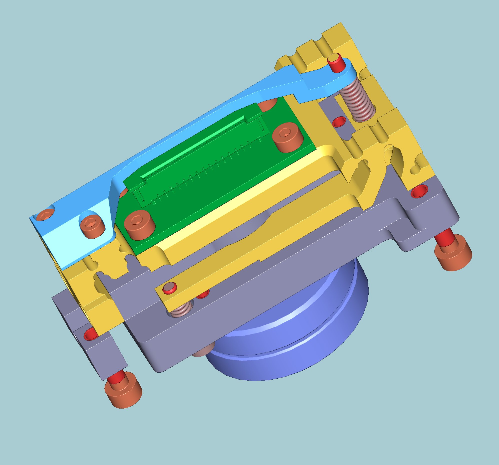
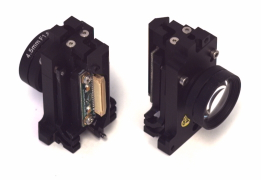
Being aware of those factors we knew that we’ll need to take care of both focusing and compensating for the non-perpendicular axis in our design – the one that you can see here both as a 3-d render and the photos of the actual assembled modules. Each module has 3 adjustment screws and arms/joints that reduce the travel of the 3 points that are attached to the sensor PCB holder 7 times.
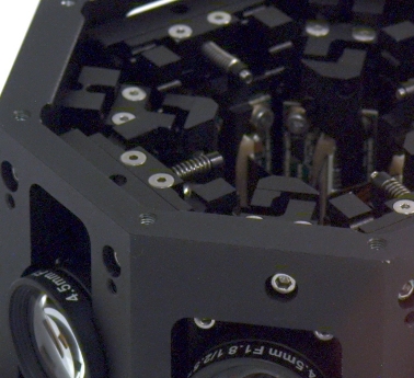 Design provides external access to the three adjustment screws (they have socket heads to simplify automatic adjustment with the small gear motors (no auto-focus while shooting imagery, just a one-time factory adjustment), the module is wider from outside and tapers inside, so when alternating orientation of odd/even units they can be fit into really tight space, providing the distance between the entrance pupils of the opposite lenses of just 90 mm (or 35 mm between adjacent lenses).
Still more challenges and setbacks
Not everything went smoothly. The fine focus/tilt adjustment module is capable of compensating for ±0.15 mm on each of the 3 points and we had completely assembled the optical heads of the first 3 prototypes hoping that the initial precision of the manufactured parts is sufficient. Unfortunately when we made the focusing software and adjustment motors drivers and started testing the sensors, we found that about half of the modules have tilt larger than than that. So we had to take everything apart and use shims to provide the initial tolerances within the adjustment range.
Measuring lens resolution
When evaluating different lenses we had to learn how to measure actual lens resolution and considered several paths. One was to use the advanced proprietary program that seems to measure many lens parameters in near-automatic mode. That could be very handy during the initial stage, but I expected to hit some problems as soon as we’ll reach any of the program limitations – I believe that even most smart programs can not anticipate all the specific tasks their users may need. One of such likely problematic areas could be integrating resolution measurements (that might need some customization) with our other software. That lead us to an open source program ImageJ and SE_MTF plugin for it that implemented Slanted Edge Modulation Transfer Function (MTF) measurement. That was a starting point, we were able to modify that code as we liked, add support for the raw Bayer data (available from the camera in JP4 format). Our software developed to work with ImageJ is maintained in Elphel git repository at Sourceforge, we also started a wiki page about this software application. SE-based MTF measurements (actually OTF – optical transfer function that includes phase information in addition to just amplitude of the MTF) was very useful for measuring lens (or sensor+lens system) but now we needed something different:
Adjusting sensor tilt and position, focusing targets
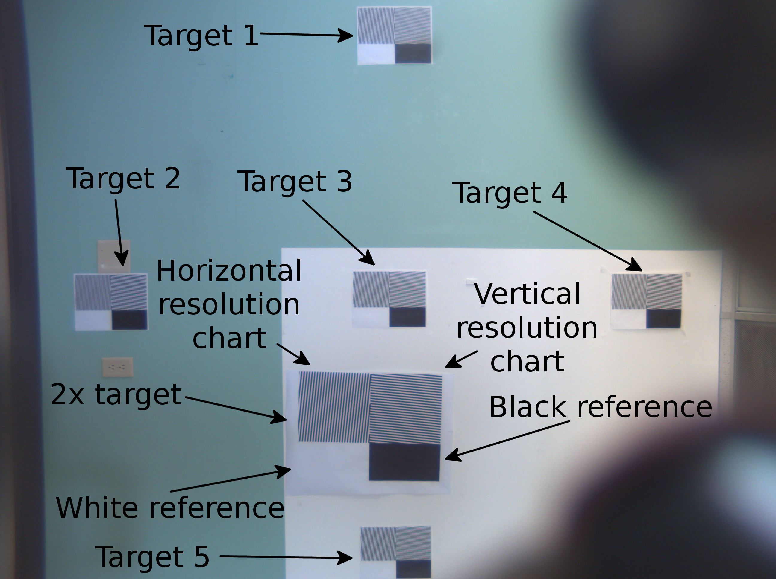 In this application we did not need to know the complete OTF through all of the spatial frequencies range, we just needed to adjust 3 parameters: one linear – distance and 2 angular – sensor tilt to the lens axis. For such measurement we used a set of 5 identical targets – one in the center and another 4 around.
Each target includes 2 areas for measuring vertical and horizontal resolution. These areas consist of parallel black and white bars at a distance that is near to 115 lp/mm (or 0.25 cycles per pixel) on the sensor.That frequency corresponds to Nyquist frequency for each individual Bayer component and each color can be processed independently. The bars are slightly tilted to spread the phase of the bars crossing pixels. Additionally each target includes large white and black areas for normalization of the contrast and reduce requirements uniformity of illumination. Software is looking for targets having specific spatial frequencies so presence of different objects in the field of view did not cause any false target detection. The program was acquiring images directly from the camera using JP46 format, the sample one corresponding to the annotated image above is here.
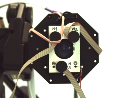
Two dark blurry objects on the right of the image are the adjustment motors, they are only used during focusing and are removed when done.
Focusing wide angle lens indoors for the objects at infinity
Most camera objects will be at infinity, taking into account depth of field the optimal distance to focus is about 10m so everything from infinity down to seven meters will be sharp. Having targets at 10 meters with 45 x 60 degrees camera field of view would require large space that we do not have,. It is also possible to rotate the camera between target measurements (using some pan/tilt platform) but we used different approach – making adjustments at shorter object distance (2.25m) and then move the sensor 7 microns towards the lens according to (1/l1+1/l2=1/f lens formula). For absolute distance calibration we used one twice larger target and focused camera on it from twice larger distance (4.5m).
Test camera setup
Originally we planned to adjust each sensor/lens pair after the all of the optical head is assembled, the adjustment motor plate is designed to reuse some of the mounting threaded holes of the head body. Unfortunately precision of the parts was slightly less than needed so we had to take all the sensor front ends (SFE) out, reassemble them and adjust separately on the test camera. In addition to the regular
- the 10353E camera system board and
- the SFE under test, the setup also includes
- a plate with 3 small 144:1 gear motors with quadrature encoders, connected to
- a simple interface board (10364) that uses camera main FPGA to implement controller for 3 motors.
That FPGA Verilog code includes de-glitchers, step counters, PWM and digital feedback that uses programmable tables, PHP and HTML files provide motor interface. The 10364 board was developed and built specifically for this application but it might be used to control compact pan/tilt motors for the camera SFE in the future designs.
In this adjustment procedure the same camera acquires images and controls the motors, when working with the assembled optical head the motors are driven by a separate camera system board.
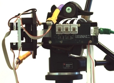 PHP control script accept a special “insert” command, when started all 3 motors perform +/-60 degree rotations so the hex shafts would fit into the socket heads of the adjustment screws. The rubber band that you can see on the photos help in this procedure and keep the motors in contact with the heads they drive, the two mounting screw are not tight and are used as guide rails.
10353 camera board as a motor controller
We planned to use motor to control the adjustment screws from the very beginning but originally considered a small Arduino board for that purpose. When we started to program it we realized that I overestimated the processing power of this small board so it turned out not easy to implement fast enough software de-glitchers for the motor encoders and create a stable feedback in the control loop so the motors will run and stop at the required position without overshooting and oscillation around. Most likely it was still possible (we could easily tolerate some 10-20 steps of the final position error), but having around so many of the familiar and easy to program 10353 camera system boards with powerful FPGA suggested to use our own product. And yes, it turned out to be rather easy – FPGA easily handles the speed of the control loom, and flexibility of handling position errors and speed is achieved by using on-chip memory block used as a run time-programmable table. PHP script initializes the driver by calculating the table elements and after that no software intervention is needed to control the motors – just to write the target position and read the current position (if needed).
Trying to focus manually
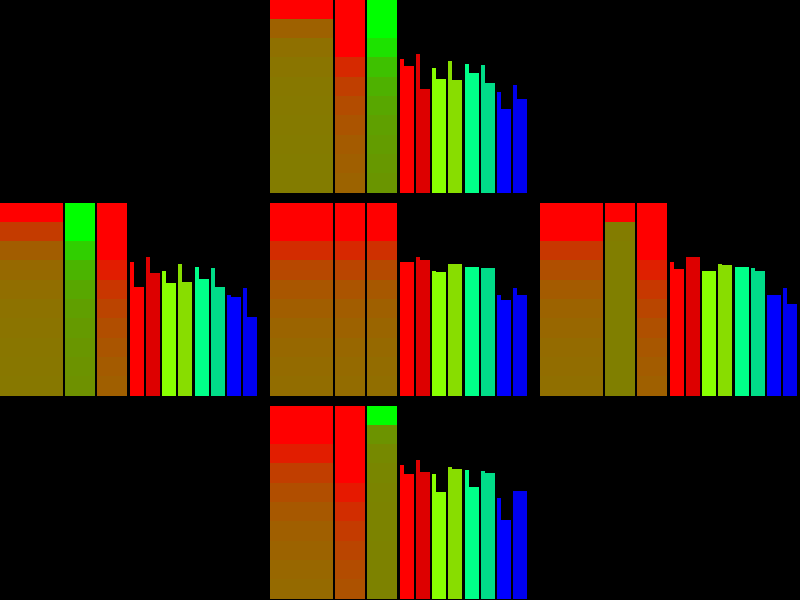
Before the motor control was ready we tested the adjustment module manually. For that purpose I made a program (as ImageJ plugin) that measures resolution on the targets described earlier and displays results in a form that was supposed to be easily interpreted. On the left side of each of the 5 target zones there are 8 color bars each representing resolution at that color (in logarithmic scale). Pairs represent resolution for vertical and horizontal patterns, yellow and cyan colors are to distinguish the two greens in Bayer pattern and narrow bars at the right of some wider ones show the best resolution for this color component/orientation among all 5 targets.
Wider bars in the middle were designed to indicate if the sensor is too close or too far. While measuring the lens resolution earlier we noticed that the lenses have noticeable longitudinal chromatic aberration and the best focus for the red color is some 6-9 microns closer to the lens than for the green color. So we planned to use that difference between color resolutions as indication of the sign and amount of the position error. The two bars in the center of each target are red if the resolution for red color is higher than that for the green one, and green if opposite is true. the top of the bar is most sensitive, the lower – the less. The widest bars on the left combine red-to-green resolutions ratios for both vertical and horizontal directions.
It works… kind of
It did work as expected for the center target, but the results on the 4 outer targets were inconsistent. When scanning through the distances to the sensor the heights of the bars did not follow the expected pattern (maximum red – too close, maximum for blue – too far and maximum green in the middle of the range). The difference between the vertical and horizontal resolutions seemed higher than difference for the colors. It did not help much when we finally connected the motors and tried to control them manually using +/- buttons. So we needed the next step – to combine resolution measurements with motor control and preform complete scans using the motors and record the per-color contrast data.
How big is the hysteresis of the adjustment system?
During the first sweeps we were looking to see how big is the hysteresis in our adjustment system. Of course, with the programmatic motor control it is easy to make it always approach destination from one side, but it is still good to have it low .
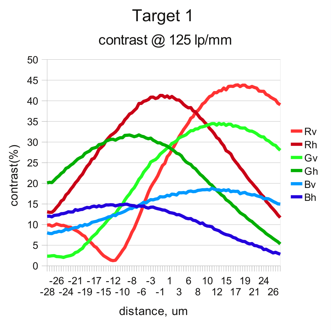
And it turned out it is low – in most cases under 2 microns, safely lower than it is needed for this application, so the next measurements were performed in a single direction and the software was performing anti-hysteresis move of 4 microns each time the required movement was in the negative direction. The first graph shows measurement results of the two scans – from -28 to +28 microns from the initial position and then – backward, from +28 to -28. That range corresponds to 5000 steps of all 3 motors rotating in the same direction, later calibrated to average of 89 steps/micron. It show results for one of the off-center targets (target 1), 6 pairs correspond to 3 colors (R, G, B) and two orientations (v,h). In each pair one is for forward sweep (F), and the other – for reverse (R).
Comparing resolution in different target zones
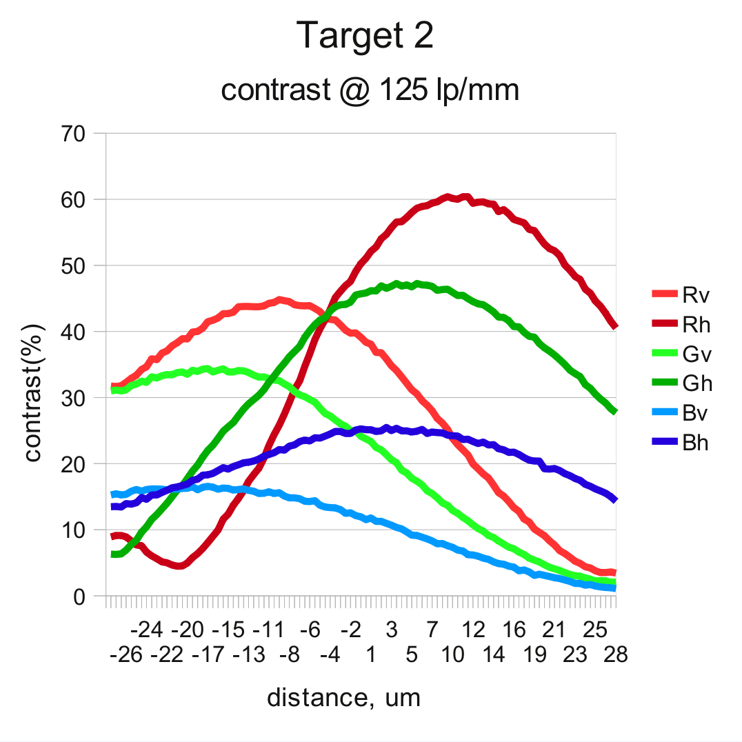
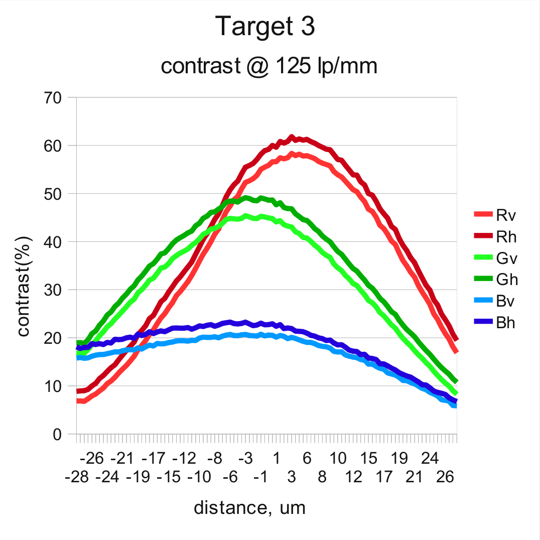
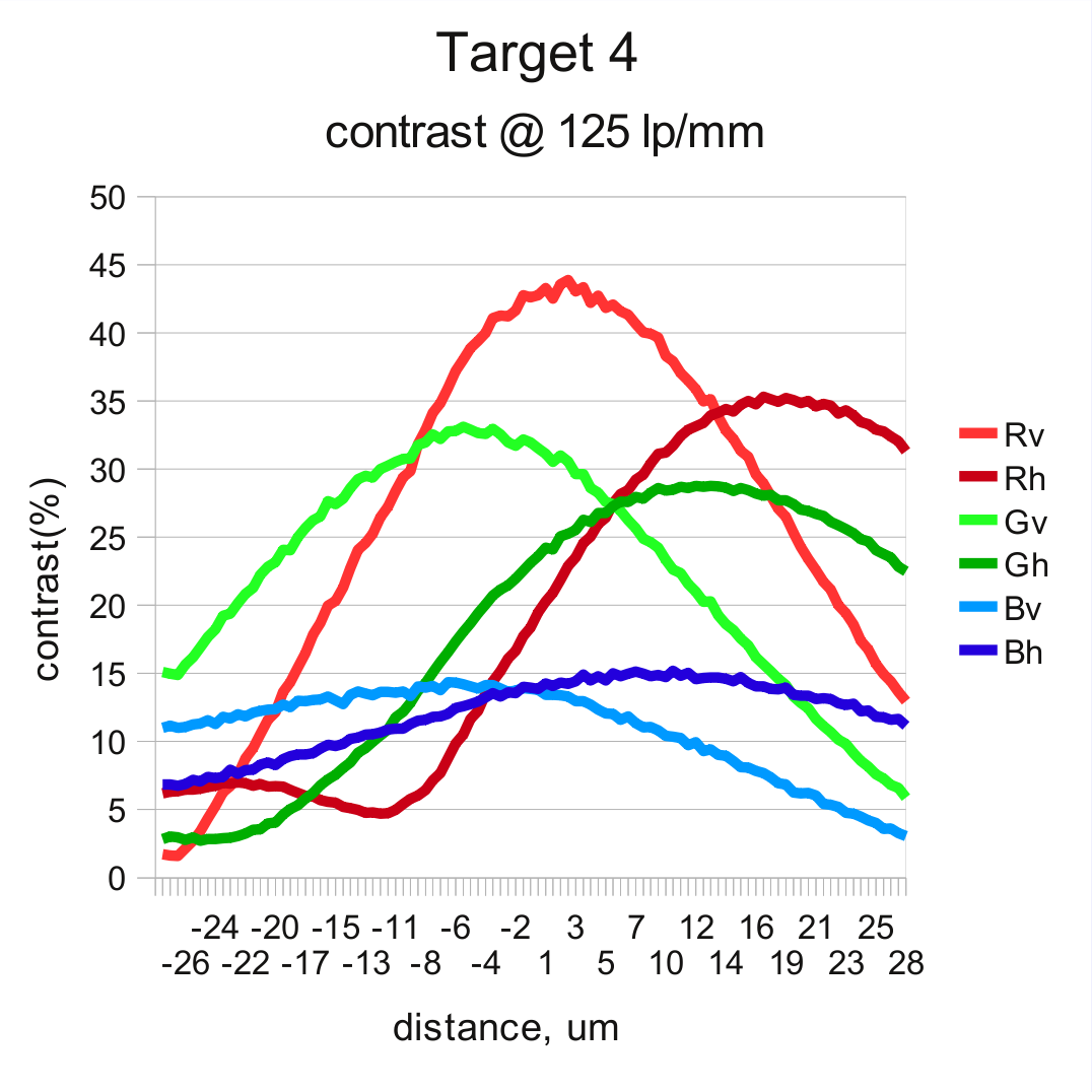
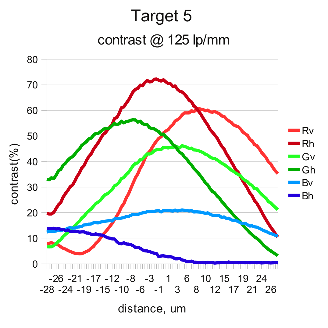
Easily predictable the best overall performance of the lens is demonstrated in the center zone (target 3). Lens exhibits low astigmatism and the curves for each color closely follows that of the same color of the opposite orientation. The pictures are quite different in the off-center zones. The resolutions in orthogonal directions split significantly, both in locations of the maximums and their relative heights. And this explains why we had difficulties when manually adjusting tilt and focus.
There is some central symmetry though – maximums for the resolution in tangential direction (for the lines fanning out of the center of the image) is achieved at more positive positions (closer to the lens) than that for radial resolution (as for the pattern of concentric circles).
 |
||
 |
 |
 |
 |
Focusing goals
With the resolution graphs differing that much the question is – what is the best position/orientation of the sensor? Which of the resolution components are more important than others?
First of all we can pin down the location of the center area – resolution there changes slowly as you move away from the center (until close to edges), and the optimum image plane location would be where the “green” resolution reaches the maximum because each other pixel in the sensor is green, there are twice more of them than the red ones. Blue color is much less important for sharpness, even human eyes are not as sharp in that spectral range. Program allows to use weighted goal that combines resolution in green and red so the final image plane is somewhat shifted from the green maximum towards the red one.
Next come the peripheral targets and the sensor tilt. The sensor itself is not flexible, of course, so moving one side (say target 2) closer to the lens and having the location of the center target2 “pinned down” the target 4 will have to move farther from the lens. Same with target 1/target 5 pair – if one moves closer, the other has to move farther.
Are the radial and tangential resolutions equally important?
With that big differences between the curves for the resolution in radial and tangential directions it is important to know how they contribute to the overall performance for this particularapplication . The lens we have is low-distortion one and does not have barrel distortion that might equalize angular resolution through the camera module FOV. As we move towards the image edge each angular degree occupies more pixels, the square shape also changes to the rectangle one. If we move horizontally, the horizontal number of pixels increase reverse proportional to the square of cosine of the angle (about 17% for the 22.5°) while vertically it is just about 8% for the same angle 22.5° . For the other direction where the full FOV is close to 60° these numbers are 33% and 15%, respectively. And we can use different weights for the values of the orthogonal resolution when calculating the goal function.
Using resolution curves for image plane distance measurements
While the measured hysteresis is low there is still substantial non-uniformity of the linear (and angular) movements of the sensor and the motor rotation steps caused by a non perfect thread, adjustment bolt heads and the surface where they are touching the adjustment module. These factors cause the transfer functions to have periodic components with the period of one screw turn that corresponds to approximately 50 μm movement of the sensor. That period is rather high, but for tilt adjustments we need to move motors in the opposite directions for larger distances. And it would me nice to be able to determine the current distance of the target images on the sensor from some reference points (defined by the goal function) – just from the sensor data itself.
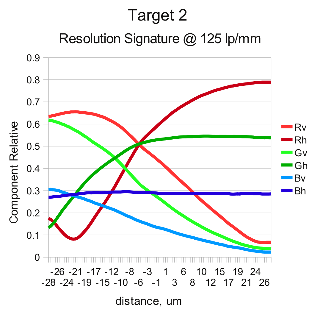
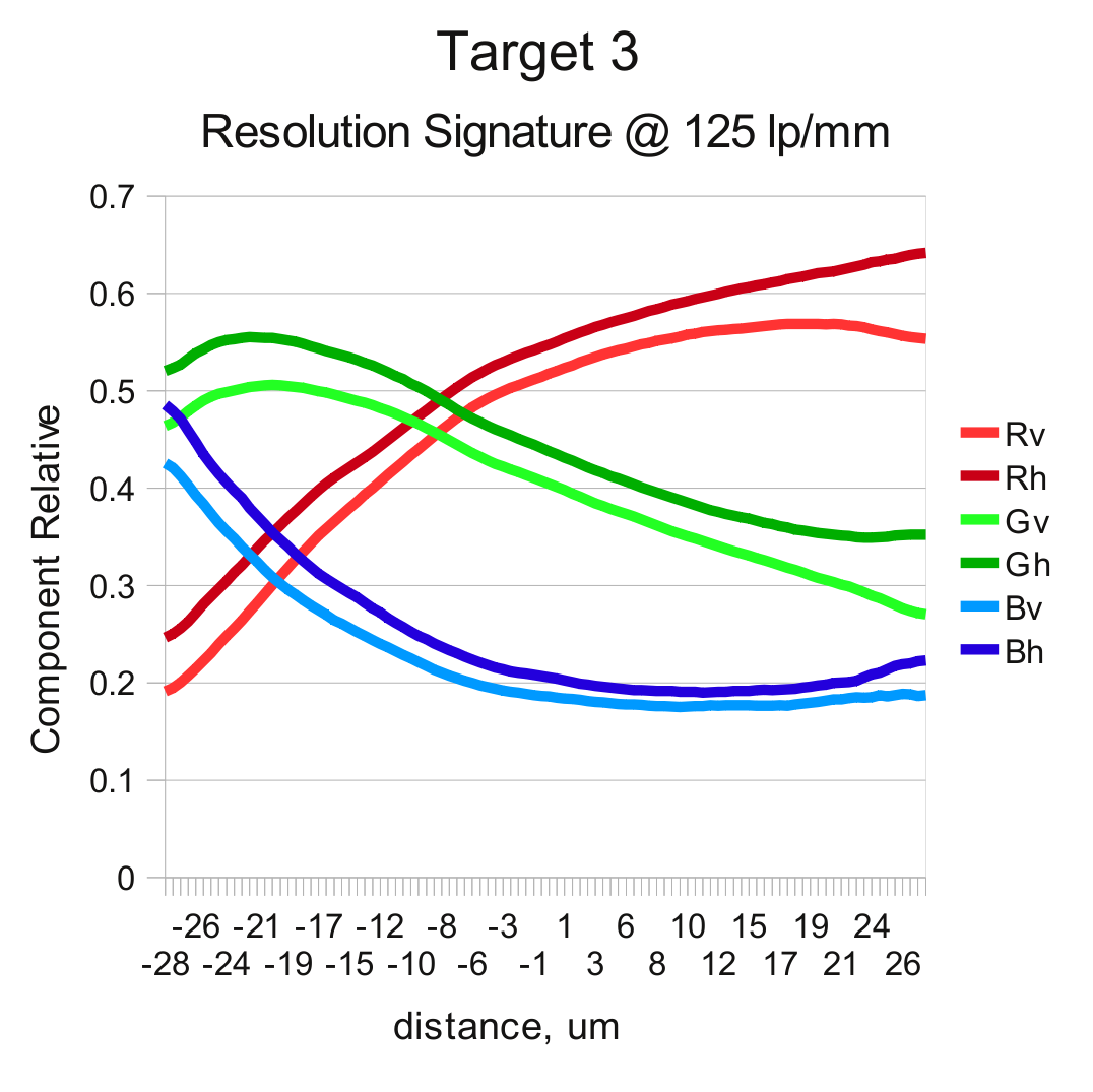
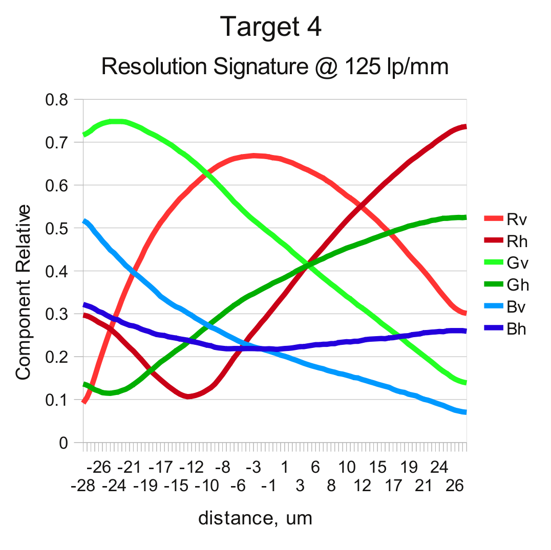
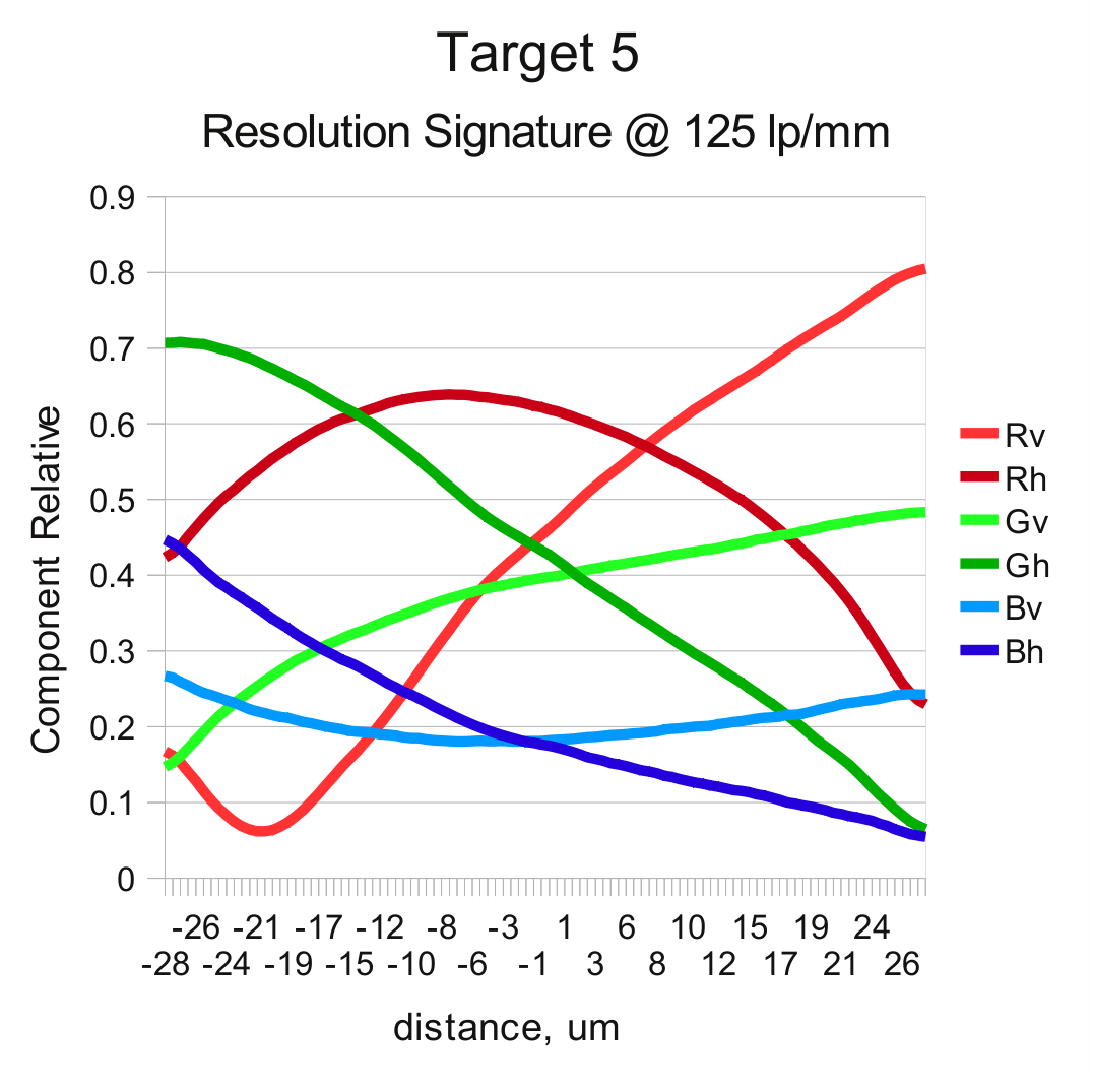
And here we can make use of the fact that lens is not ideal and the resolution curves for different colors and orientations do not follow each other. First we take the resolution data represented by the previous plots and normalize each component by dividing it by square root of the sum of component squares. That creates “signature” curves useful to identify location on the x-axis (distance from the reference point) using the measured set of 6 components.
When the new image (with unknown image plane location) is acquired each target gives a vector of 6 components. First we can find the X-value by determining the minimal value of the distance from the measured vector and all of the calibration ones (represented as curves on the graphs below). That distance have minimum but it may be not very narrow, measurement precision is also influenced by multiple sources of noise, we can use the second calculation stage to improve the calculations.
The second stage involves taking two reference vectors from the calibration data at some distance before and after the preliminary found maximum and then interpolating the result by comparing the new measured sample and the two reference vectors using weighted differences, with the weight proportional to the absolute value of the particular component difference of the reference vectors. For example, if the reference vectors are in the region where there is a steep slope on the say Gv component while Bv and Rh are nearly horizontal, then the interpolation will primarily rely on the Gv difference and disregard Bv and Rh values.
 |
||
 |
 |
 |
 |
Where we are now
As I wrote above we did have some problems with the precision of assembled SFE modules and had to take them all out and apart, now we are retesting them one-by-one before the final assembly of the panoramic camera head. It took us much longer than we hoped (as it usually happens) but it seems the results are great – when we turned the finally adjusted camera modules (corrected to 10m object distance) and pointed them outdoors – the image looks great, even in the off-center areas. And resolution of the optics match that of the 5 megapixel sensors that are used in the camera.
We are really looking forward to get the complete panoramic image of all the camera modules making photos simultaneously.
Wow – that is “rocket science” – in the most positive, accessible way. Congratulations to your achievements!