Capturing Aircraft Position with the Long Range Quad Stereo Camera
Figure 1. Aircraft positions during descent captured with the quad stereo camera. Each animation frame corresponds to the available 3-D model.
While we continue to work on the multi-sensor stereo camera hardware (we plan to double the number of sensors to capture single-exposure HDR image sets) and develop code to get the ground truth data for the CNN training, we had some fun testing the camera for capturing aircraft position in 3-D space. Completely passive method, of course.
We found a suitable spot about 2.5 km from the beginning of the runway 34L of the Salt Lake City international airport (exact location is shown in the model viewer) so approaching aircraft would pass almost over our heads. With the 60°(H)×45°(V) field of view of the camera aircraft are visible when they are 270 m away horizontally.
Camera was set to capture synchronized image sets at 5 frames per second (same as in Fig. 1 animation), each set was processed independently without any relation to the other ones (no optical flow or motion vectors). Our existing (not airplane-aware) prototype software generated the scene 3-D models, they in turn were used to measure the aircraft positions. Result accuracy may be improved by using directly the intermediate Disparity Space Image (DSI) data – current reconstruction code tries to fit some flat surfaces to approximate the DSI data. At long distances there is insufficient data about the shape of the objects, so at ~500 m range (Fig. 2) the software used a fronto-parallel surface (distances to the aircraft nose, center, and tail are the same) and at ~600m it selected a tilted surface in the wrong direction, so the measured distance to the tail is larger than the one measured to the nose and center.
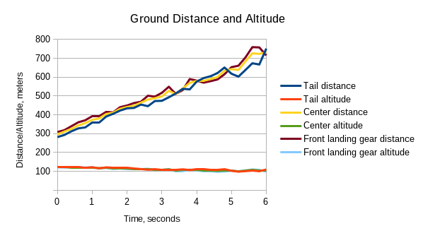
Figure 2. Ground distance and altitude of the three points sampled.
The measurements accuracy is still good, considering that the disparity of 1 image pixel corresponds for this short baseline camera to 527 meters range, at 800 m 1/10 pixel disparity precision corresponds to 120 m uncertainty. Ground speed and the descend rate (indicated in the animation) are calculated between the first captured set and the current one, so the last value averages over the full 6 seconds.
This method of capturing aircraft position and speed does not require that it travels directly to/from the camera, it can fly in any direction. There could also be multiple aircraft (such as UAVs) in the same camera view. Another 3-D scene (Fig. 3) captured from the same spot perpendicular to the flight direction shows an aircraft at 1600 m from the camera at 110 m altitude. According to the map the center line of the 34R runway is 14% farther (at 1820 m) from the camera position. That corresponds to 0.045 pix disparity error in the distance measurement, so calculated ground speed and altitude would also be 14% lower than actual.
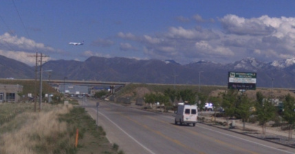
Figure 3. Aircraft traveling perpendicular to the view direction.
Each of the provided 3-D scene models has the corresponding “set of 4 images” link on the settings page that can be viewed as an animation, manually iterated over or downloaded – the one for Fig. 3 scene shows how a 0.33 pixel wiggle of the FedEx MD-11 image looks like (images are zoomable and pannable). Here are the direct links for image sets of the first (1.75 pix disparity) and the last (0.7 pix disparity) of the scene models of the approaching B737 shown in Fig. 1.
These four images are not used in the actual reconstruction process, they are rendered from the source raw (JP4 format) ones for the specified disparity (D0.0 in the file names show that disparity was 0.0 pixels) for viewing or evaluating with alternative software. These images are not rectilinear and have residual common (for all four) radial distortion. They have optical aberrations corrected by the space-variant deconvolution, sub-camera residual misalignment is field-corrected (such misalignment may be caused by an uneven heating of the camera tubular structure by the direct sunlight). The images are partially rectified to the common radial distortion model that bests fits simultaneously all four sub-cameras. The remaining radial distortion is compensated during final generation of the 3-D model. These images have visible grid artifacts caused by the Bayer pattern – no de-mosaic processing is involved because it hurts linear operations over the images, and it is not adequate for the peripheral image areas (see earlier post). Each color component is processed separately for the phase correlation, when combining texture images these artifacts are reduced as they are not coherent between the channels. Any additional non-linear improvements of the Bayer mosaic suppression can be applied to the texture generation step, not to the data used for correlation.
Leave a Reply