Implementing a linux driver for an image sensor for NC393
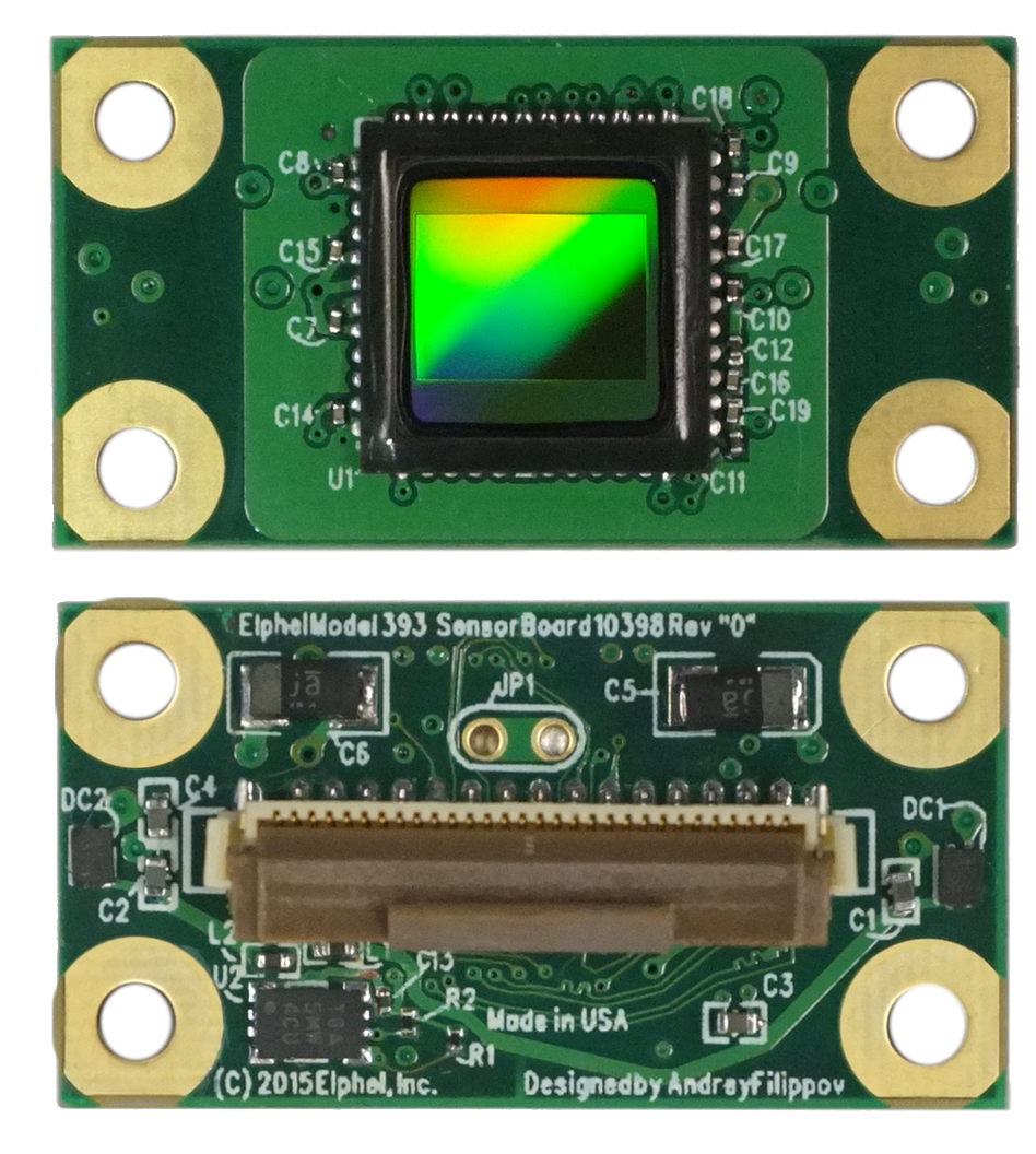
Fig.1 MT9F002
MT9F002
This post briefly covers implementation of a driver for On Semi’s MT9F002 14MPx image sensor for 10393 system boards – the steps are more or less general. The driver is included in the latest software/firmware image (20180416). The implemented features are programmable:
- window size
- horizontal & vertical mirror
- color gains
- exposure
- fps and trigger-synced ports
- frame-based commands sequence allowing to change settings of any image up to 16 frames ahead (didn’t need to be implemented as it’s the common part of the driver for all sensors)
- auto cable phase adjustment during init for cables of various lengths
Setup
- Get the register reference document for MT9F002
- Setup the Eclipse IDE for linux kernel development – see instructions
Capturing images without the driver
There is a set of scripts used for verification in software (on PC) and hardware (on the target board). Among other things they can be used to establish initial communication with a sensor, run registers initialization and acquire the first images. The process for MT9F002 is described on our wiki.
Driver implementation
In general the driver can be split into 2 parts:
- common for all sensors – sets up working with fpga frame-based command sequencers (see NC393 development progress and the future plans).
- sensor specific – commands that do actual communication with a sensor. This is the part needs to be implemented.
For a sensor there are a few tables and a few functions, the most important ones are:
tables:
- mt9f002_pages – a ‘page’ is the upper byte of a 16-bit register address of the sensor (for 8-bit reg addresses the page number is 0x00), the table should list all available pages in the sensor – or at least the most important ones – they are used to program fpga’s 256-max records per port tables used to write commands and at least one record is used to read from port – so in general for a setup w/o a MUX board the limit of allowed pages per sensor is 256-1 = 255 (with a MUX + 3x sensors on a single port it is 256-2(mux write & read)-4(3x sensor read + 1x broadcast read))/4 = 62)
- mt9f002_par2addr – used convert 256 8-bit parameters available as P_SENSOR_REGSxxx to 16-bit register address
- mt9f002_ahead_tab – sequencer commands latencies – leave default, they are needed on the final stages of development
functions (they are registered on top of the common ones):
- mt9f002_pgm_detectsensor – remove reset read sensor id
- mt9f002_pgm_initsensor – init registers that select interface, sensor’s PLL multipliers/dividers and other required settings
- mt9f002_pgm_exposure – program exposure
- mt9f002_pgm_window – program image width and height
- mt9f002_pgm_limitfps – limit fps based on compressor capabilities and trigger period settings
- mt9f002_pgm_gains – program color gains
- mt9f002_pgm_triggermode – set sensor in triggered mode
- mt9f002_pgm_sensorregs – write sensor registers directly
See this article for more details.
Leave a Reply