Using a flash with a CMOS image sensor: ERS and GRR modes
Operation modes in conventional CMOS image sensors with the electronic rolling shutter
Flash test setup
Most of the CMOS image sensors have Electronic Rolling Shutter – the images are acquired by scanning line by line. Their strengths and weaknesses are well known and extremely wide usage made the technology somewhat perfect – Andrey might have already said this somewhere before.
There are CMOS sensors with a Global Shutter BUT (if we take the same optical formats):
- because of more elements per pixel – they have lower full well capacity and quantum efficiency
- because analog memory is used – they have higher dark current and higher shutter ratio
Some links:
- CCD and CMOS Sensor Architecture and Readout Modes (nice pictures)
- Image sensors and shutter related artifacts
- Rolling Shutter (Wikipedia)
So, the typical sensor with ERS may support 3 modes of operation:
- Electronic Rolling Shutter (ERS) Continuous
- Electronic Rolling Shutter (ERS) Snapshot
- Global Reset Release (GRR) Snapshot
GRR Snapshot was available in the 10353 cameras but ourselves we never tried it – one should have write directly to the sensor’s register to turn it on. But now it is tested and working in 10393s available through the TRIG (0x14) parameter.
MT9P001 sensor
Further, I will be writing about ON Semi’s MT9P001 image sensor focusing on snapshot modes. The operation modes are described in the sensor’s datasheet. In short:
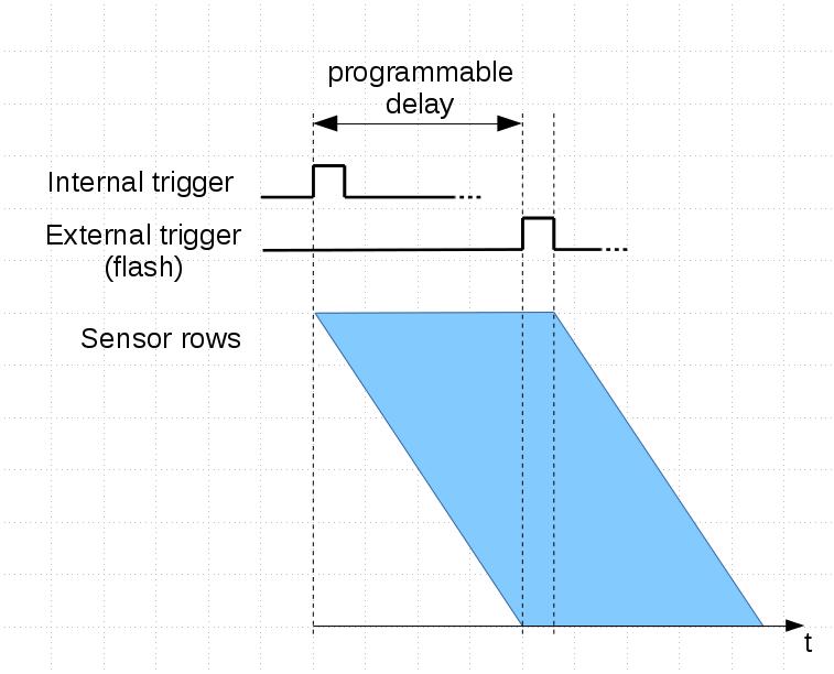
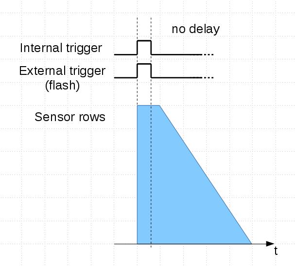
In ERS Snapshot mode (Fig.1,3), exposure time is constant across all rows but each next row’s exposure start is delayed by tROW (row readout time) from the previous one (and so is the exposure end).
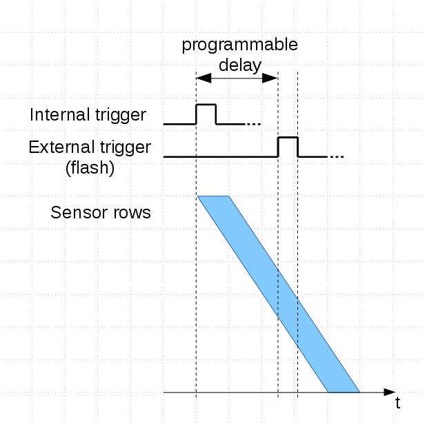
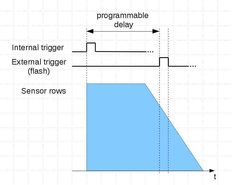
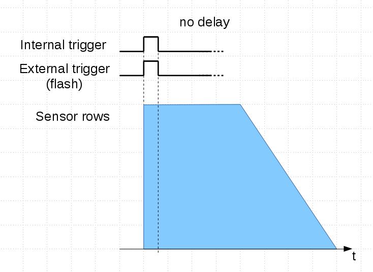
In GRR Snapshot mode (Fig.2,4), the exposure of all rows starts at the same moment but each next row is exposed by tROW longer than the previous one. This mode is good when a flash use is needed.
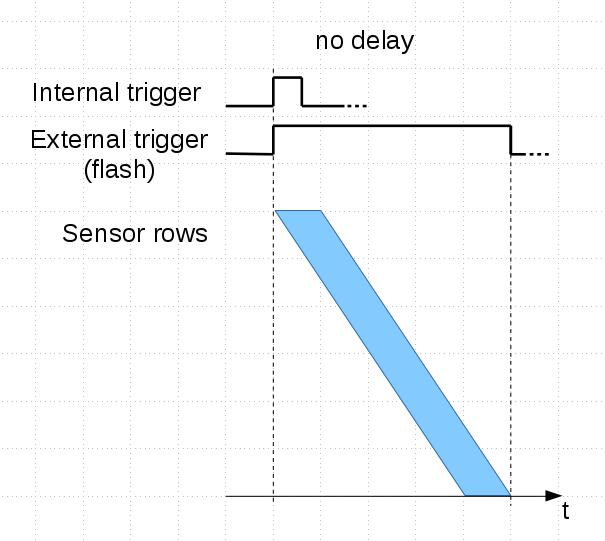
The difference between ERS Snapshot and Continuous is that in the latter mode the sensor doesn’t wait for a trigger and starts new image while still finishing reading the previous one. It provides the highest frame rate (Fig.5).
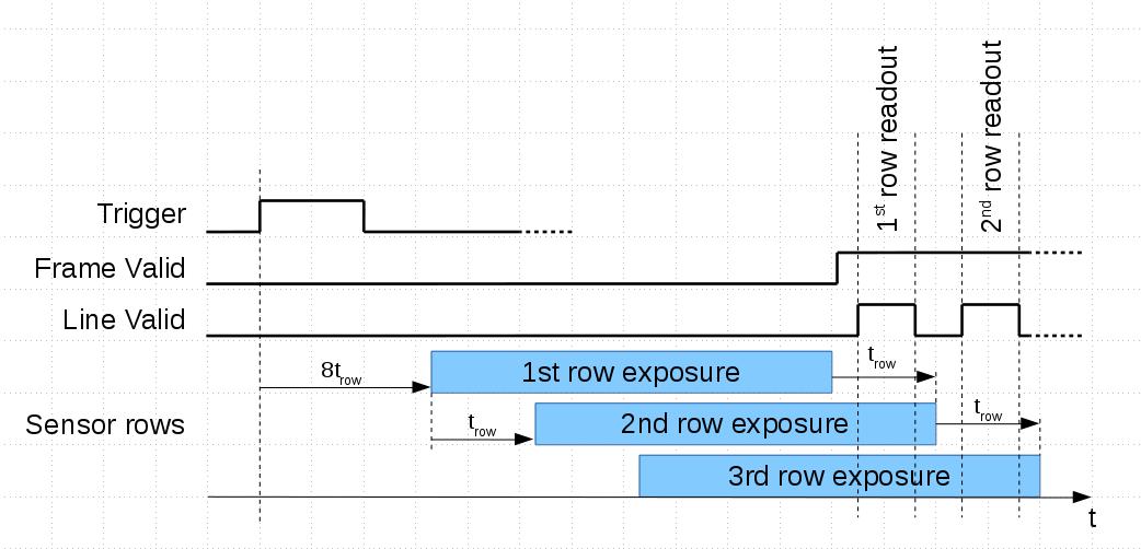 Fig.1 Electronic Rolling Shutter (ERS) Snapshot mode |
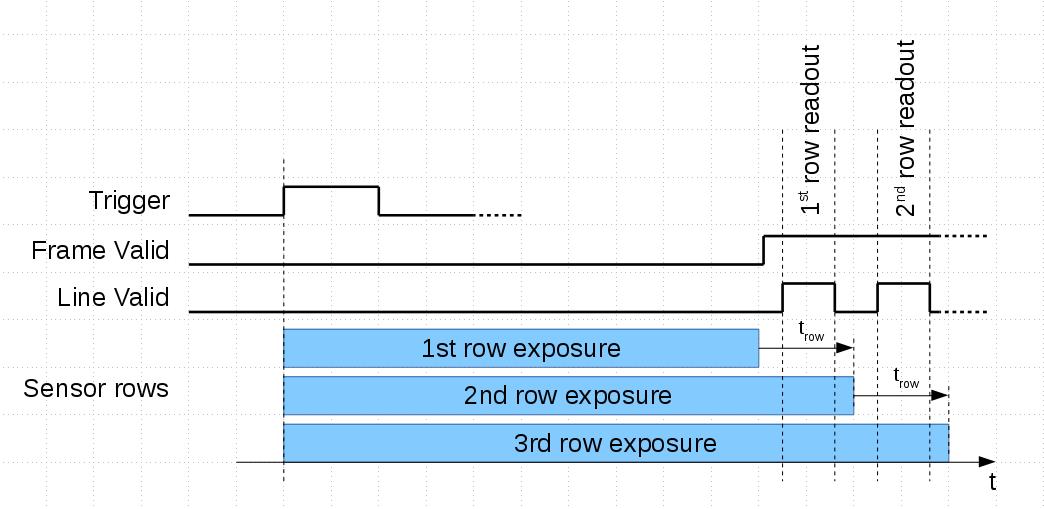 Fig.2 Global Reset Release (GRR) Snapshot mode |
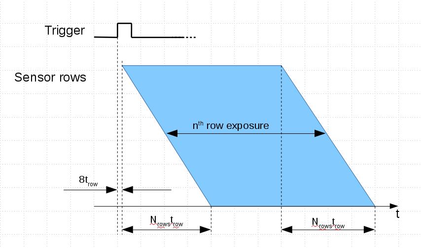 Fig.3 ERS mode, whole frame |
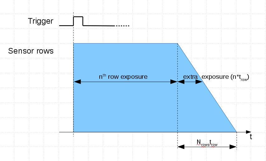 Fig.4 GRR mode, whole frame |
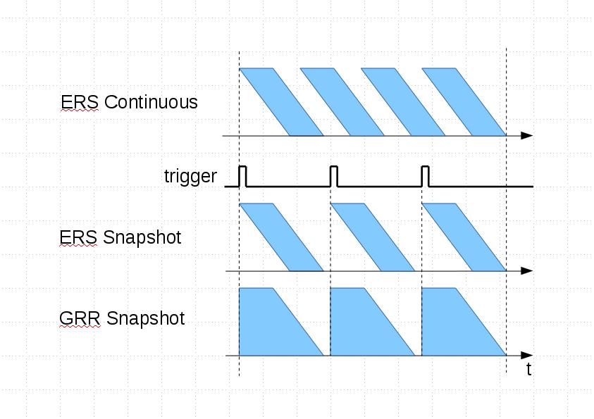 Fig.5 Sensor operation modes, frame sequence |
Here are some of the actual parameters of MT9P001:
| Parameter | Value |
|---|---|
| Active pixels | 2592h x 1944v |
| tROW | 33.5 μs |
| Frame readout time (Nrows x tROW) | 1944 x 33.5 μs ~ 65 ms |
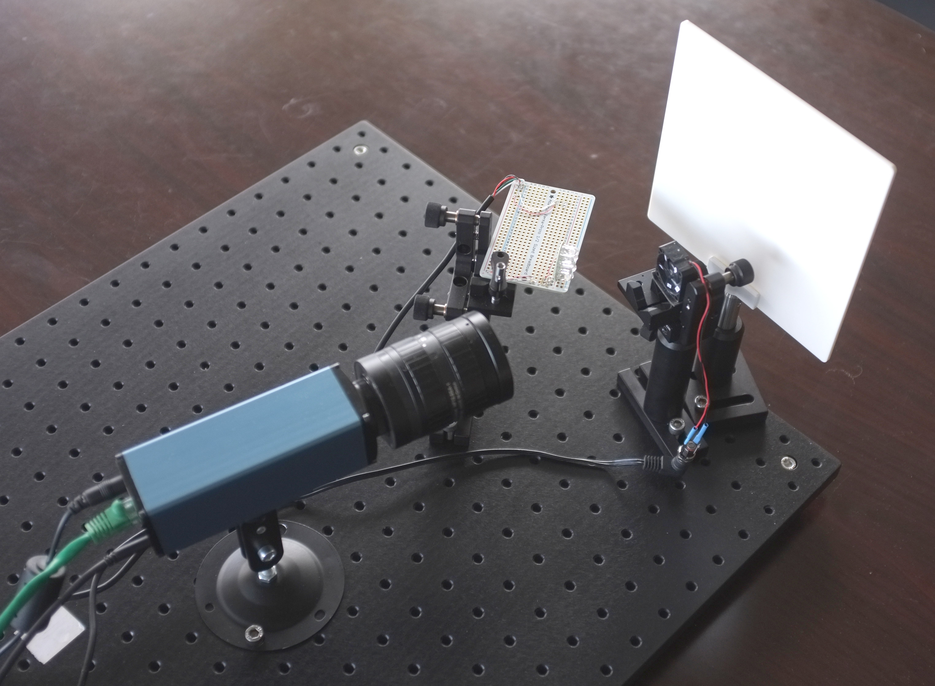
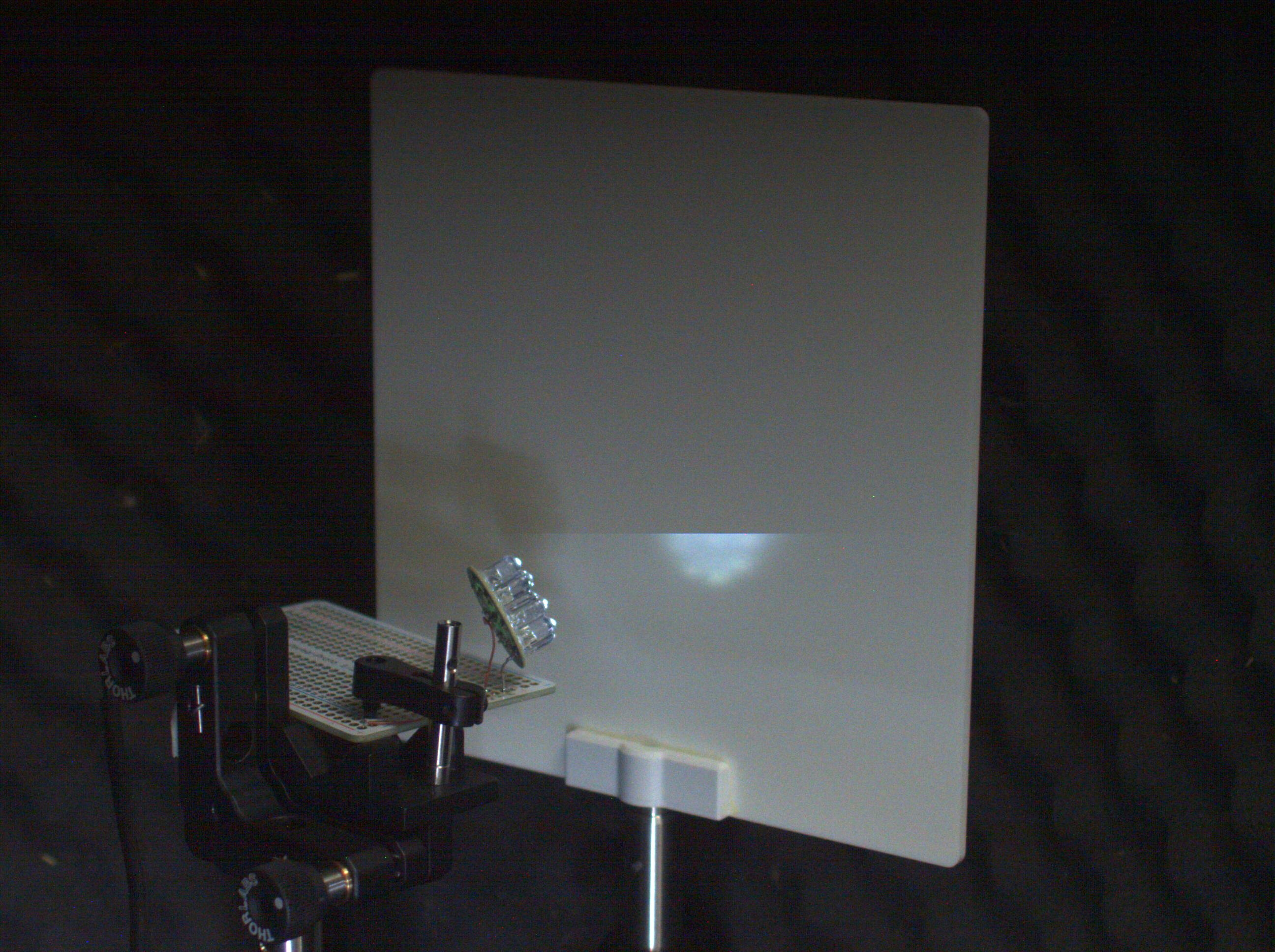
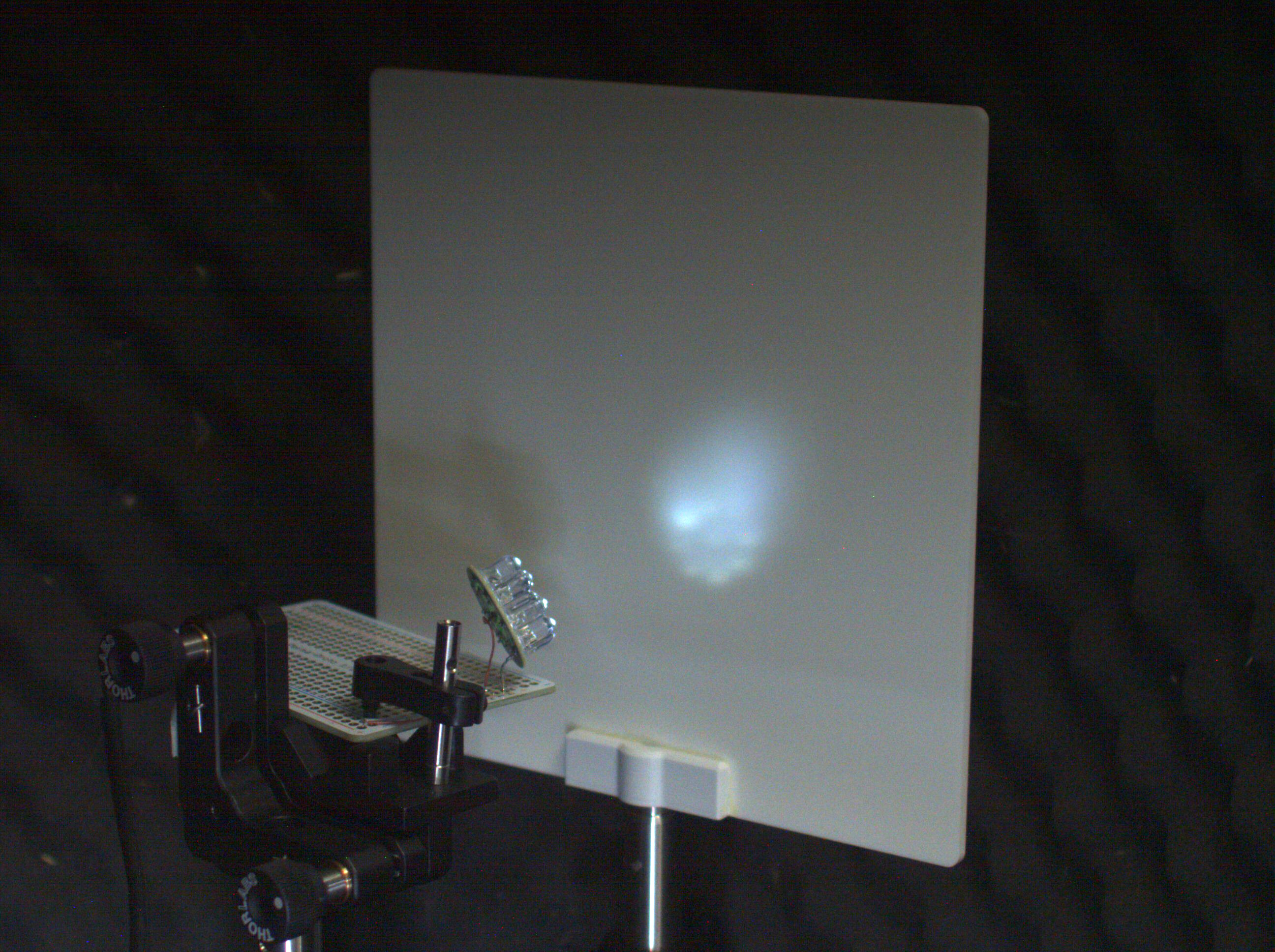
Test setup
- NC393L-389
- 9xLEDs
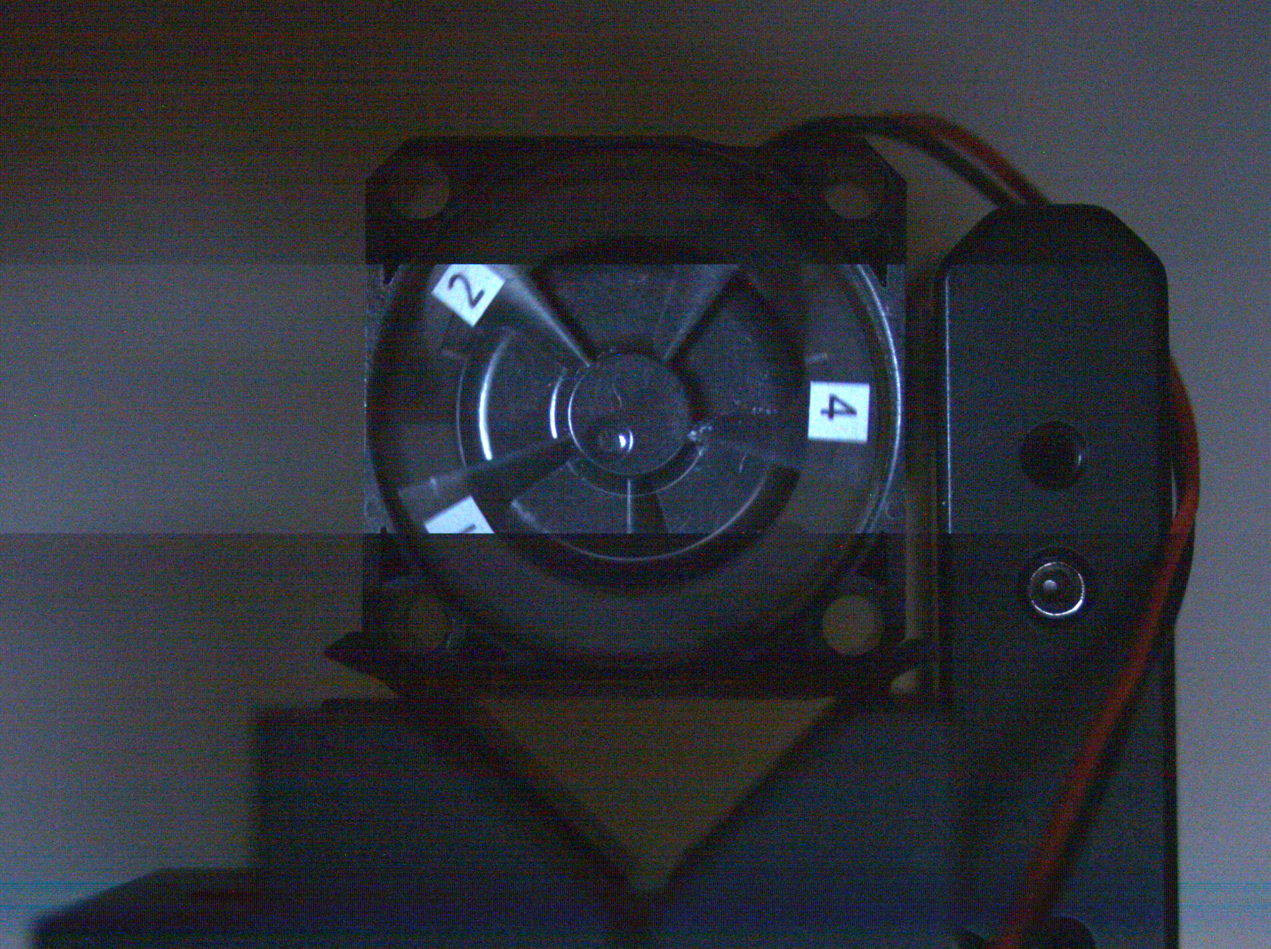
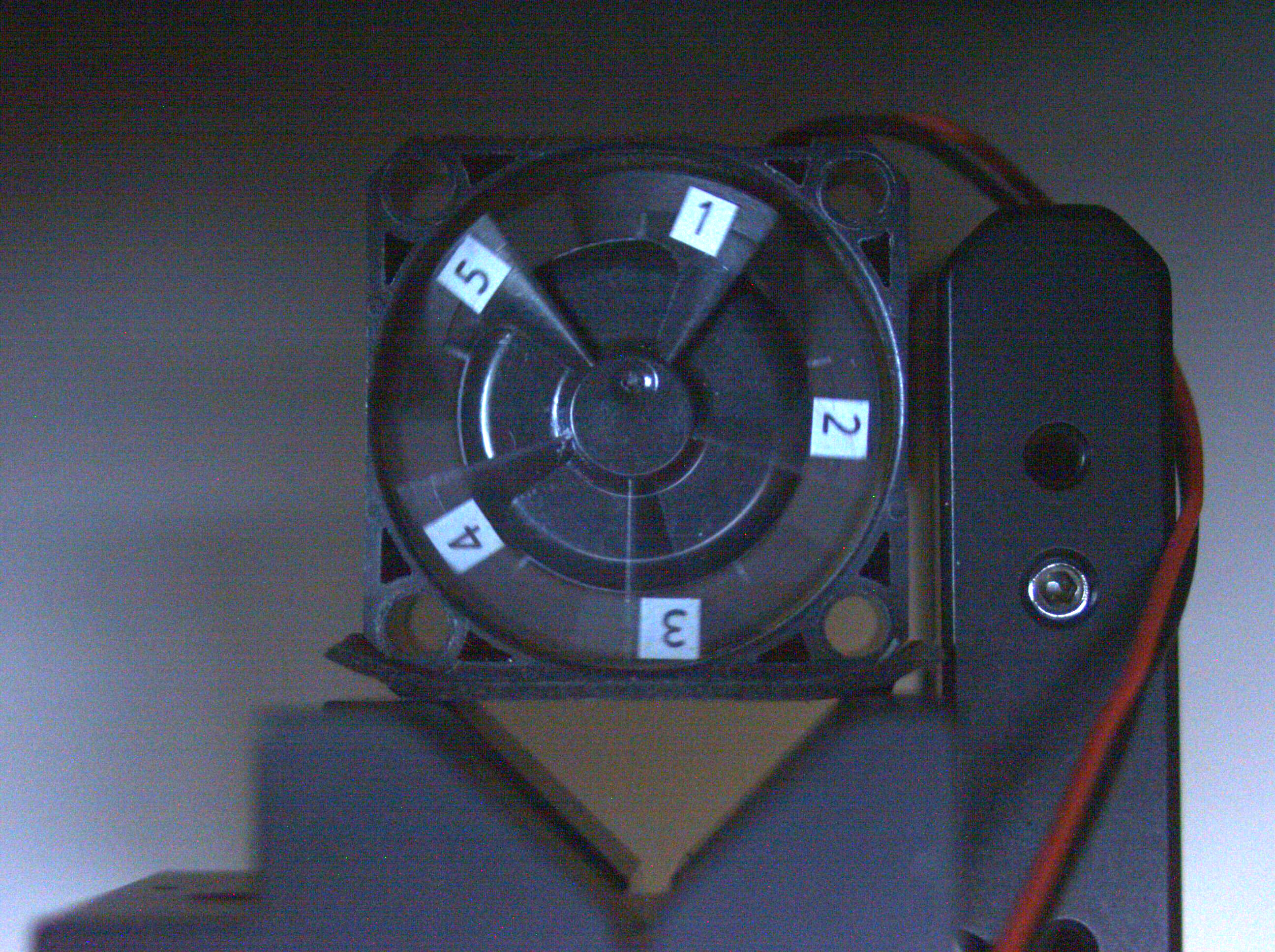
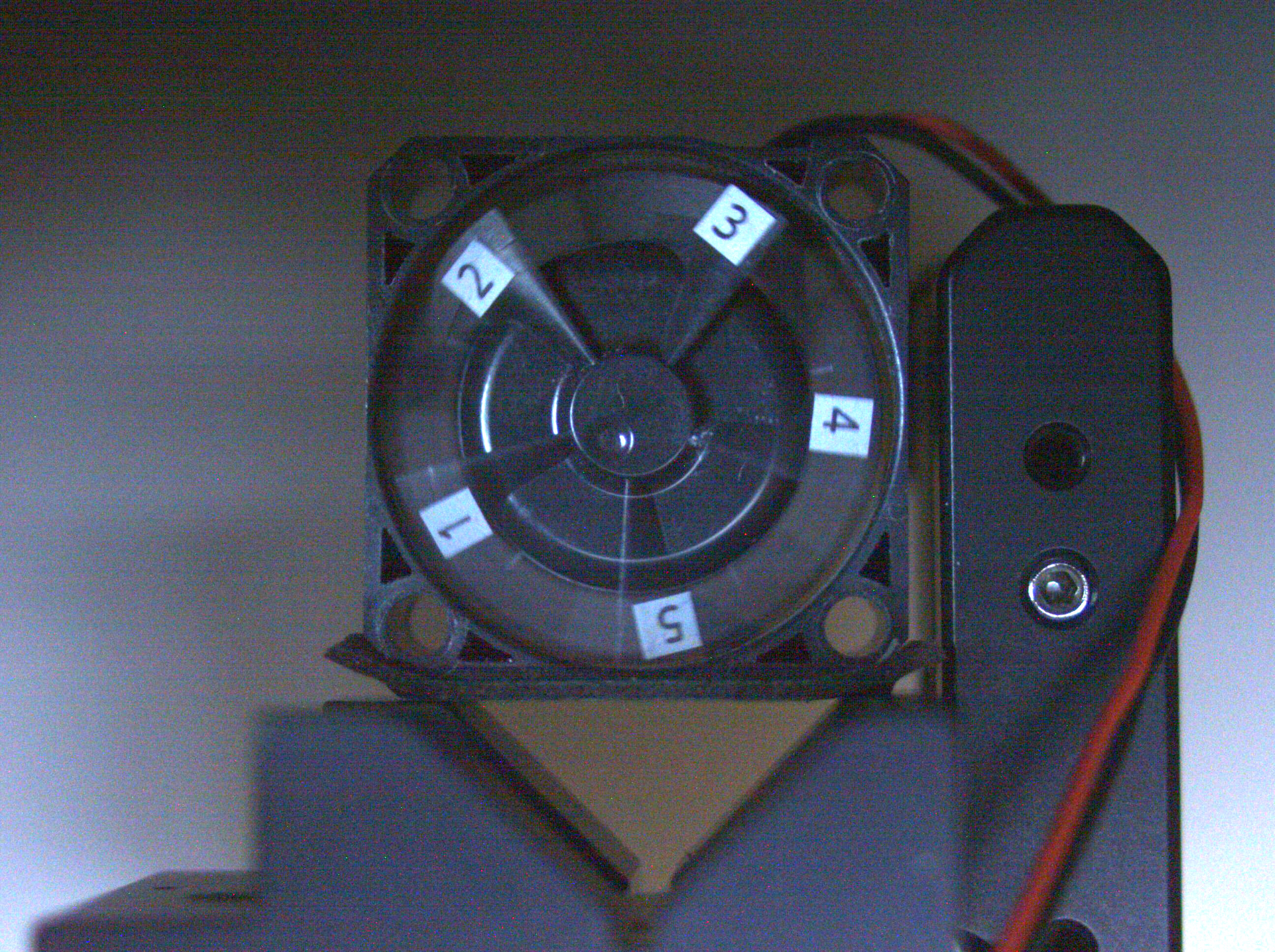
- Fan (Copal F251R, 25×25 mm, rotating at 5500-8000 RPM)
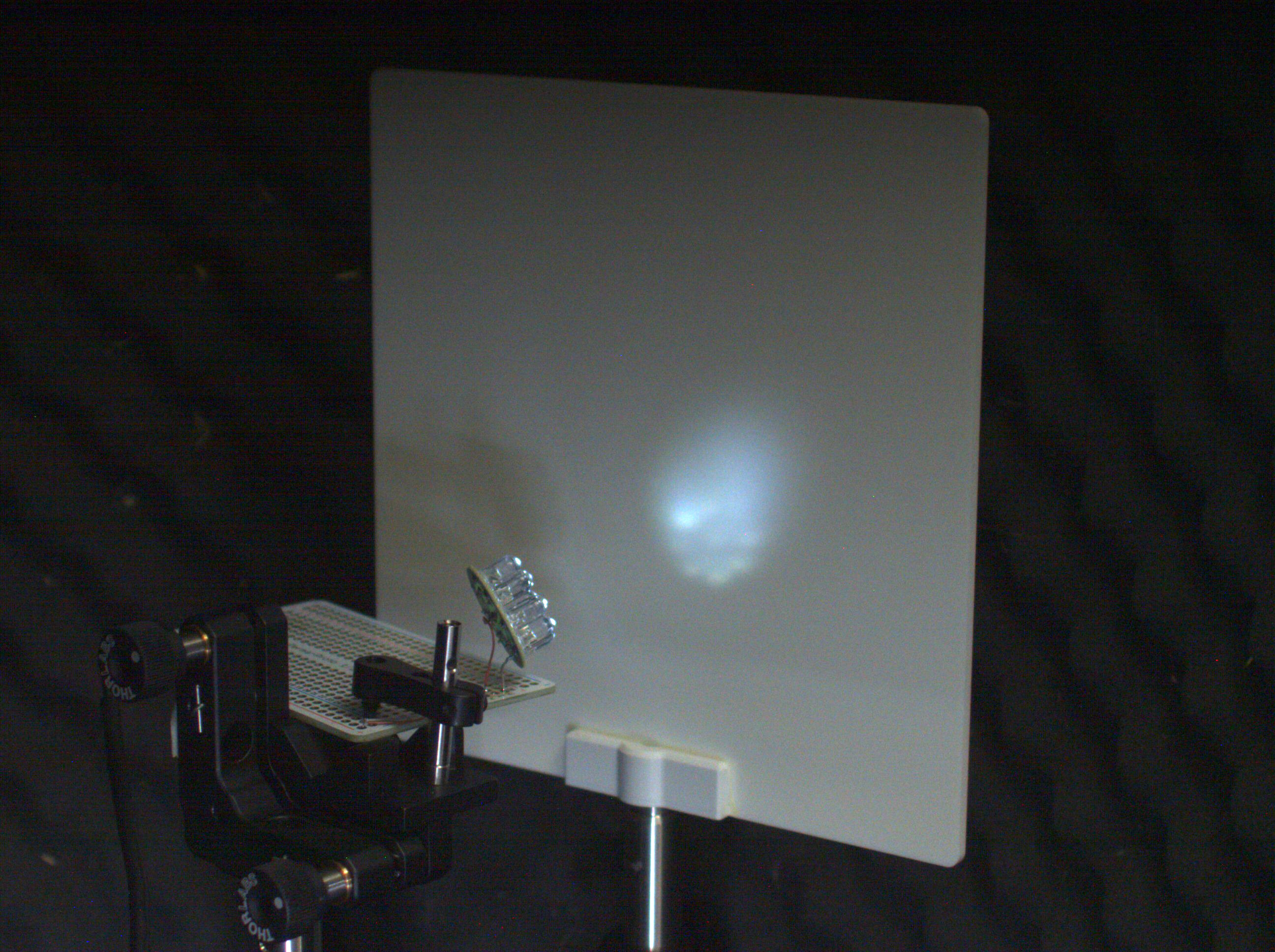
The LEDs were powered & controlled by the camera’s external trigger output, the delay and duration of which are programmable.
The flash duration was set to 20 μs to catch, without the motion blur, the fan’s blades are marked with stickers – 5500-8000 RPM that is 0.5-0.96° per 20 μs. There was not enough light from the LEDs, so the setup is placed in dark environment and the camera color gains were set to 8 (ISO ~800-1000) – the images are a bit noisy.
The trigger period was set to 250 ms – and the synced LEDs were blinking for each frame.
The information on how to program the NC393 camera to generate trigger signal, fps, change sensor’s operation modes (ERS/GRR) can be found here.
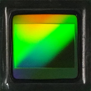
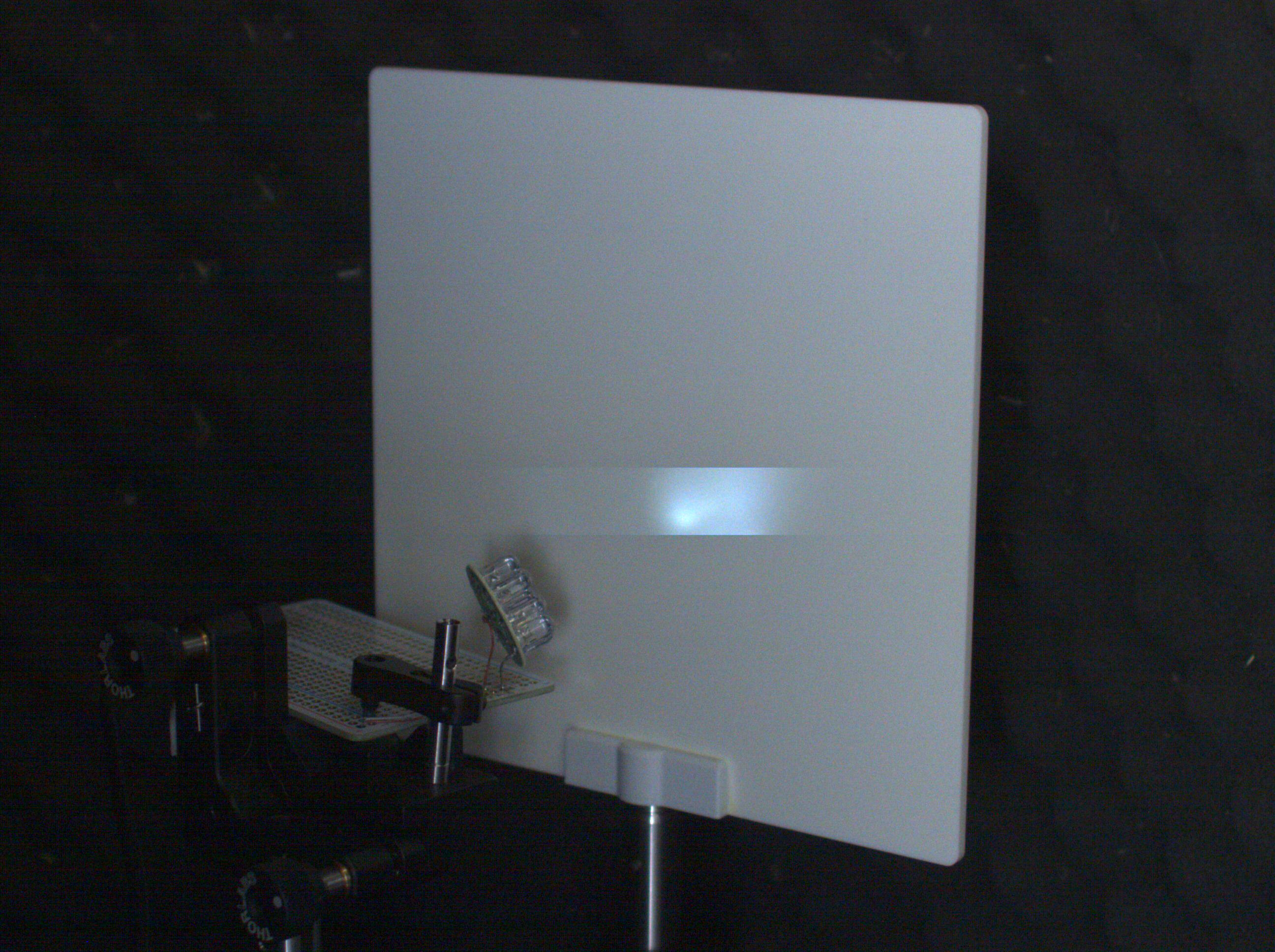
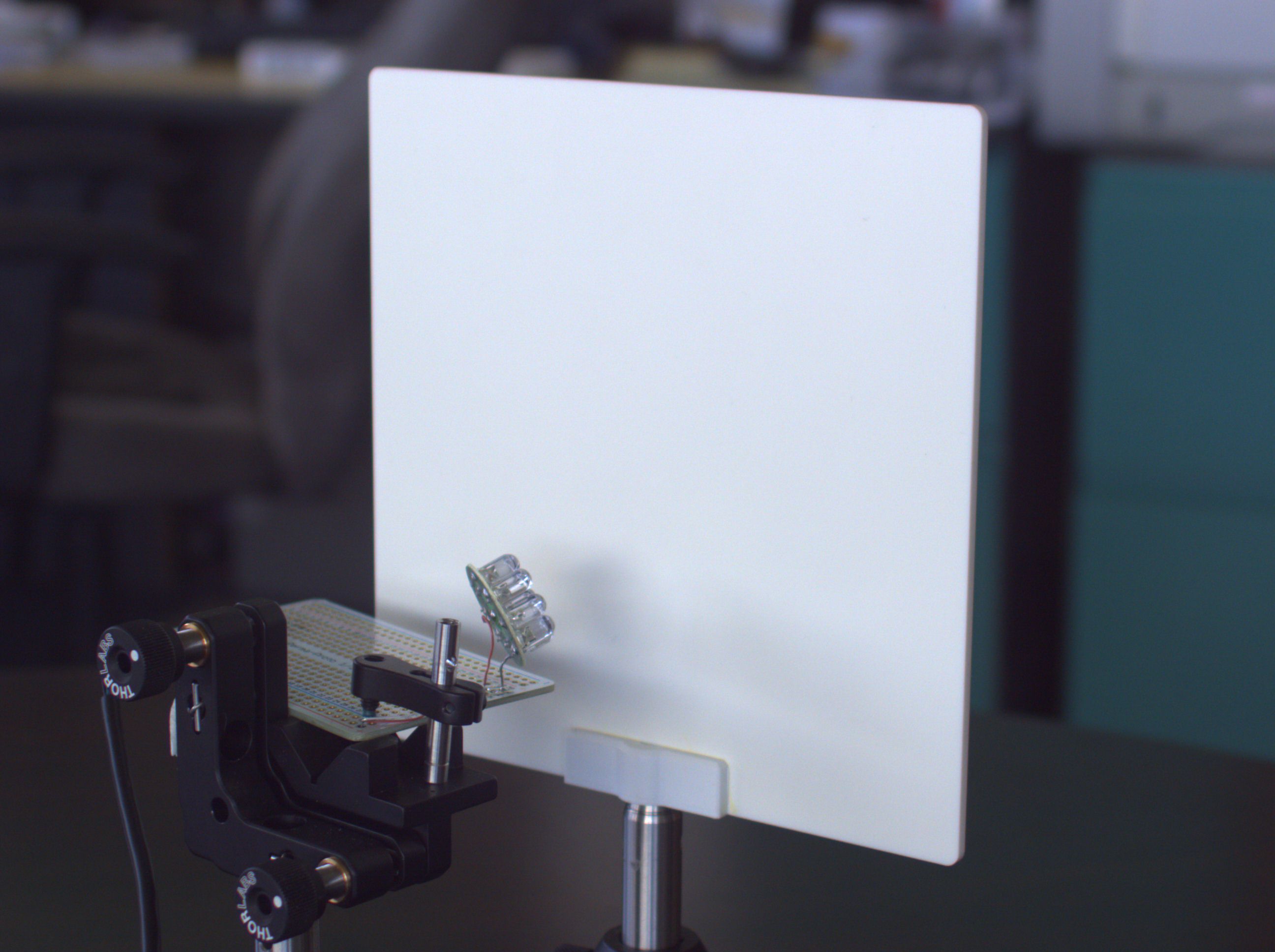 Fig.6a Setup: screen, camera view |
Fig.6b Setup: fan |
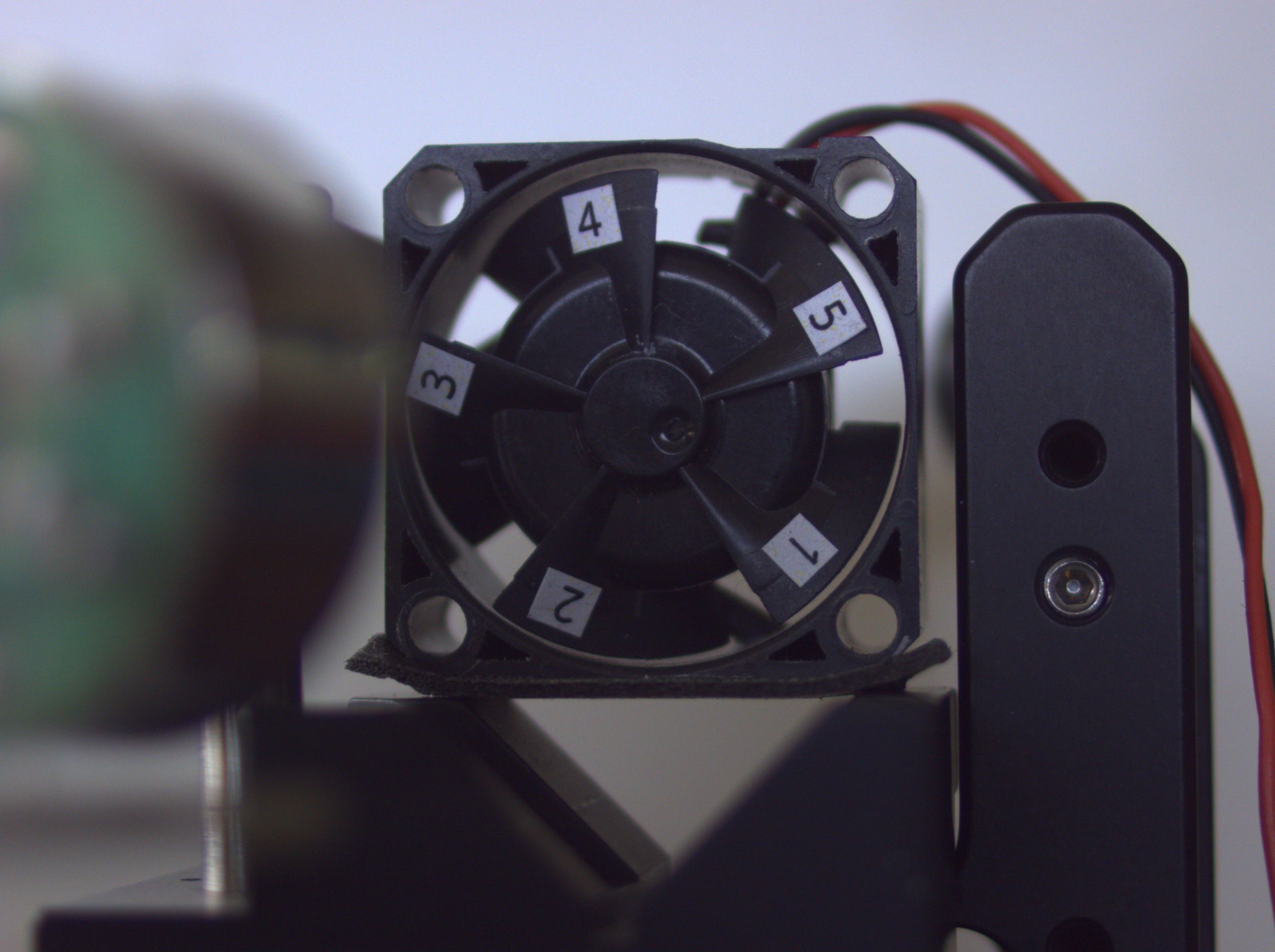 Fig.6c Setup: fan, camera view |
Flash in ERS mode
 |
 |
 |
| Fig.7a | Fig.7b | Fig.7c |
In Fig.7a to expose all rows to the flash the exposure needs to be programmed so the 1st row’s end of exposure will exceed the last row’s start of exposure and the flash delayed until the exposure start of the last row. That makes the single row exposure 72ms+tflash.
Note: there is no ERS effect for moving objects – provided, of course, that the flash is much brighter than the other light sources that will be reducing the contrast during the 72ms frame time.
In Fig.7b the exposure is shorter than the frame readout time – the flash delay can be any – the result is a brighter band on the image as shown in the example below.
Another way to expose all rows is to keep the flash on from the 1st row start until the last row end (Fig.7c) – that’s as good as keeping the flash on all the time.
Example:
| Diagram | Screen | Fan |
|---|---|---|
|
 |
 |
| Exposure time, ms | 5 | 20 |
| Flash duration, ms | 0.02 (20μs) | 0.02 |
| Flash delay, ms | 40 | 40 |
| Comments | The fan blades are motion blurred in the rows not affected by the delayed 20μs flash. The flash delay is set so the affected rows appear in the middle of the image. Exposure time defines the width of the bright rows band. |
Flash in GRR mode
 |
 |
| Fig.8a | Fig.8b |
In GRR mode the flash does not need to be delayed and the exposure of the 1st row can be as low as tflash but the last row will be exposed for tflash+72ms (Fig.8a). If the scene is uniformly illuminated the the image tends to be darker in the top and getting brighter in the bottom. GRR is very useful with a flash lamp.
Note: No ERS effect (as in Fig.7a case).
Fig.8b just shows what happens if the flash is delayed until frame is read out.
Examples:
| Diagram | Screen | Fan |
|---|---|---|
|
 |
 |
| Exposure time, ms | 0.1 | 0.1 |
| Flash duration, ms | 0.02 | 0.02 |
| Flash delay, ms | 40 | 30 |
| Comments | The fan blades are motion blurred in the rows not affected by the delayed 20μs flash. All of the rows not read out before the flash are affected. |
| Diagram | Screen | Fan |
|---|---|---|
|
 |
 |
| Exposure time, ms | 0.1 | 0.1 |
| Flash duration, ms | 0.02 | 0.02 |
| Flash delay, ms | 0 | 0 |
| Comments | Fan is rotating. No motion blur. In GRR if flash is not delayed the whole image is affected by the flash. Brighter environment = lower contrast. |
| Diagram | Screen | Fan |
|---|---|---|
 |
 |
 |
| Exposure time, ms | 5 | 10 |
| Flash duration, ms | 0.02 | 0.02 |
| Flash delay, ms | 0 | 0 |
| Comments | Fan is rotating. 100 times longer exposure compared to the previous example – the environment is relatively dark. |
Conclusions
- ERS Continuous – max fps, constant exposure, not synced
- ERS Snapshot – constant exposure, synced
- GRR Snapshot – synced, use this mode with flash
Links
- How to program 10393 parameters: ERS/GRR, fps, output trigger delay to sync with flash or else, trigger duration
Terrific explanation, thanks for posting that.