Building and Calibrating Eyesis4π
This is a long overdue post describing our work on the Eyesis4π camera, an attempt to catch up with the developments of the last half of a year. The design of the camera started a year before that and I described the planned changes from the previous model in Eyesis4πi post. Oleg wrote about the assembly progress and since that post we did not post any updates.
Sensor front end challenges
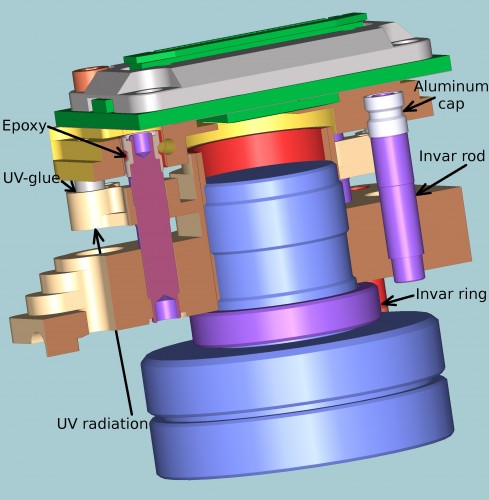
Working on the first camera of this series we had to solve several technical problems – and that push us back behind our schedule. First problem was with the use of the UV-curing adhesive to fix the sensor relative to the lens. In the first Eyesis we incorporated some elements of the sensor adjustment into each SFE (sensor front end), in the current system we decided to follow a more traditional approach and adjust the sensor on a specialized device and then fix the position with the adhesive – that allowed us to make the SFE more compact and we hoped to simplify it too. In the new design I tried to reduce the thickness on the UV-curable adhesive and make the system self-compensating for the glue shrinkage during curing and thermal expansion of it when the camera is used. The solution used 3 pins in 3 holes with the glue between the pins and the walls of the holes, so expansion/contraction of the adhesive would not lead so significant movement of the pins. Unfortunately the illumination of the glue with the UV radiation proved to be insufficient (some shadow areas remained) and the UV LED were on the same side of the glue where it contacted the air, so the most illuminated areas suffered from the “oxygen inhibition”. We tried several small modifications but still could not achieve reliable and strong bonding we needed. So we decided to use just low-shrinkage epoxy instead of the UV glue the first camera and leave more radical redesign for later time. With epoxy we could make only 2 SFE in 24 hours, because the curing took much longer than the UV glue and we could not use fast-setting epoxy as the adjustment took some time. That method was slow but it worked. Worked until we decided to measure the temperature dependence of the focusing and realized that just maintaining the SFE “in focus” over the intended temperature range is not sufficient for our application where we compensate for the lens aberrations with post-processing. The measured temperature coefficient was about 0.2μm/°C – that corresponds to 10 mm of the expanding aluminum – material used in most of the SFE.
Thermally compensated SFE design
We could not think of any quick fix to that problem so we decided to go through the complete redesign of the sensor front ends used in Eyesis4π cameras, add thermal compensation and improve bonding process. Some elements of the SFE are made of invar – nearly zero expansion material for the thermal compensation, the bonding is spit into two separate stages – fast UV bonding and final using low-shrink epoxy. Additionally we modified the 10338D sensor front end PCB (the new version has revision “E”) to include the temperature sensor. Luckily for us we just had to replace a single chip – instead of the serial EEPROM the new board uses a combination of the EEPROM and a temperature sensor in the same size package and pinout (such chips are used in computer memory modules to store module parameters and monitor temperature). The new board simplifies temperature dependence measurements of each SFE during manufacturing, it also makes possible to do perform additional thermal correction of the acquired images – the SFE temperature during acquisition is embedded in the Exif header of each of them.
The 0353-07-25 SFE has two major parts – the base with the attached lens and the movable (during adjustment) plate to which the sensor PCB is attached. These two parts are connected with the 3 invar rods, each being press-in (and then flared) in the base. Only the very bottom part of the rod is press-fit, most of it is loose so the thermal expansion of the aluminum base is isolated from the rod. The base has 3 arms that are partially cut through to allow some bending, these arms support the invar rods laterally while allowing the axial movement caused by the thermal expansion. The top of each invar has aluminum cap pressed on and flared, these caps fit (with the sufficient clearance to guarantee co-contact during adjustment process) inside the holes in the sensor plate and are later bonded with the epoxy compound. Each of the 3 arms that provide lateral support of the invar rods additionally have 3 through holes that are temporarily plugged at the bottoms with the transparent adhesive tape to hold UV-curable adhesive. The sensor plate has 3 thin-wall stainless steel tubes pressed in it, these tubes are immersed in the adhesive and bonded to the base arms when irradiated with UV from the bottom during curing. The SFE is mounted in the adjustment machine with the lens pointed down, the mirror mounted at 45 degree reflects the target pattern located on the vertical wall. The same mirror reflects the UV radiation during curing process after the adjustment is finished. The 2.8mm invar spacer ring (for expansion it is in-series with the rods) is designed to slightly over-compensate the thermal expansion of the aluminum parts, so it can be made of different material (or a combination of 2 washers made of different materials) to fine-tune the overall expansion. This design allowed to reduce the thermal variance of the distance between the sensor and the focal plane of the lens by nearly an order of magnitude – the measured value falls in ±0.03 μm/°C range.
SFE compensated for the purpose of the aberration correction that maintains the same position of the lens focal plane relative to the sensor surface still has some magnification variations caused by the sensor expansion itself among other factors. It is not large – until we upgrade camera to the higher resolution sensors the change for 10°C is only 0.08 pixels for the diagonal corners of the image, this effect can be easily compensated when the temperature during acquisition is known.
Camera calibration machine
Camera calibration involves the following procedures:
- measuring the point spread function (PSF) for each area of the field of view of each sensor to be able to compensate for the aberration during post-processing of the acquired images
- measuring distortions of each lens and precise orientation and position of each lens in the camera assembly so the result images have the pixels precisely mapped to the lines in space
- measuring the vignetting of each lens including variations of color reproduction over the area of each sensor
- logging the inertial measurement unit (IMU) data
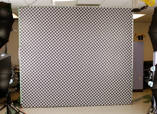
All the optical measurements (first three) are made with the same target pattern described in the earlier post. When performing the distortion measurements the camera can be located rather close to the pattern, but for the aberration measurement and correction it should be within the depth-of-field range from infinity – distance at which the camera will operate. In our case it is 6 meters. With the individual sub-camera FOV of 45°x60° the target pattern would have to be 5m (horizontal) by 7m (vertical) to fill the sensor completely. As it is not easy to make and use such large target we developed software to combine PSF data from multiple overlapping images of a smaller pattern – we used 3022mm by 2667mm that fits on the wall in our office.
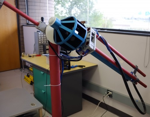
When calibrating the earlier Eyesis model that had just 9 sensors we manually rotated the camera on a photographic tripod and were making at least 12 shots for each sensor. For the Eyesis4π with full sphere FOV and with the long tube body that can not be detached during calibration (it has essential electronic boards and the two bottom sensors on it) the regular tripod would not work. So we had built a special device that allows rotation of the camera around to axes – horizontal (it goes approximately through the center of the camera optical head) and the vertical axis of the camera. As the camera is capable to view at nadir (along the tube body) the camera is rotating in the polyurethane rollers that do not block the view of the target along the tube.
When the PSF are calculated during post-processing it does not matter what part of the pattern is visible – the ideal pattern is locally distorted for the best fit with the acquired images and then used in deconvolution to calculate the aberration correction kernels, minor geometric errors in the pattern and non-flatness of the pattern surface are not critical. But the same is not true when we perform the distortion measurements and precise pixel mapping – in that case the stretching of the pattern panels, non flatness would cause significant errors. In this case the pattern is treated as a 3-d mesh of the pattern cells with arbitrary coordinates of each of the nodes, these coordinates are determined during bundle adjustment with the camera parameters. The post-processing in this case should not just fit ideal pattern to the measured images, but have an absolute match (same cell to the same cell) between the wall pattern and the acquired images.
There are several methods to achieve such matching. One is to add special marks to the pattern or just some non-periodic elements that would allow unambiguously determine what part of the whole pattern is visible. That would work for the purpose of the PSF measurement – if the pattern marks are recognized they can be included in the simulated pattern being used for de-convolution. We used a different approach – projecting spots by the 4 red diode lasers to the white pattern cells at some distance from the corners.These lasers are under software control so multiple images with different state of the lasers are recorded and used for absolute matching of the actual and acquired pattern, the final image is made with all lasers off, so pattern is not influenced by them.
The distortion calibration for individual sensors is described in an earlier post – Subpixel Registration and Distortion Measurement – it uses Levenberg-Marquardt algorithm (LMA) to simultaneously fit the whole camera orientation/position as well as individual lens/sensor parameters. The calibration machine allows acquisition of multiple sets of 26 simultaneous images, for the full calibration we record about 450 sets to have good overlap – each area of each sensor has the target visible on at least 4 images, after filtering out images that did not capture the view of the target pattern there are about 1500 images to process. It is essential that while the overlap between different sensors FOV is small (under 10%) the same target pattern is visible by multiple sensors on many image sets images, this allows to determine mutual location/orientation of the sub-cameras and finally find out the coordinates of each lens in the camera coordinate system.
Before the image data is processed farther, these images are converted to arrays of pattern grid pixel coordinates using absolute grid cell numbers if laser pointers were detected or just relative if the pointers are not available. Images without laser pointers data are still useful – they are processed when the program has enough information (from another images) to predict where the pattern nodes are expected.
The calibration measurement takes about 10 hours – the laser pointers are detected from 6 images (to increase signal-to-noise ratio) and those images are discarded, only a single images with laser pointer metadata is preserved, this processing accounts for the most of these 10 hours procedure. We perform it overnight to reduce requirements to completely block the daylight and avoid disturbance from shaking the floor. And still the processing discovers small number of images that do not fit with others (usually by under 0.3 pixels) – that is most likely caused by semi-trucks going over the speed bump right by our building. Luckily such disturbances are present on very few images and it is easier to use software to detect and remove them than to provide a complete vibration-free calibration environment.
Parameters that are determined during fitting with LMA include:
- position and orientation of the calibration machine relative to the target,
- distance and angle between the two camera rotation axes,
- locations and orientations of the individual lenses relative to the camera coordinate system
- lens (distortion) parameters for each channel – focal length, lens center coordinates, radial distortion polynomial coefficients and
- the two rotation angles of the calibration machine
All the parameters but the last ones (the two rotation angles) are assumed to be the same during the calibration process, the last ones are individual for each calibration set. Overall there are sup to 1500 of the simultaneously optimized variables using five to six millions data points of the reprojection error – differences (measured in pixels) between the pattern grid nodes on the images and the ones calculated from the actual target nodes coordinates and the camera model. When the algorithm converges to a set of parameters, we calibrate the target pattern itself. this is needed because the calibration pattern is printed on the material that can stretch and is not perfectly flat. Target calibration involves measuring and recording 3d coordinates of each cell, this is done by multiple iterations of referencing reprojection errors from multiple images to the individual pattern cells, calculating and applying those corrections and then repeating the LMA. After several iterations the root mean square (RMS) of the reprojection error reaches 0.3-0.5 pixels. At this stage the lens focal length, center and the radial distortion coefficients (fifth-degree polynomial) are frozen and the program encodes the residual differences as an array of X and Y corrections over the area of each sensor. We also repeat this procedure several times interleaving it with LMA that excludes the “frozen” lens parameters. This additionally reduces the RMS error down to 0.07-0.09 pixels.
Flat-field data for each sensor is measured to compensate for the lens vignetting and minor color variations caused by the sensor mosaic filter, it does not include individual pixel differences. Such data is measured with the same calibration pattern as aberrations and distortions. With the camera rotation steps we use the pattern is visible in each of the sensors in some 30-40 individual shots, each centered at different areas of the target. Assuming constant illumination intensity between measurements this allows to calibrate the relative illumination (and color variations) of the target cells and then use this data (averaged over all sensors) to determine each sub-camera sensitivity over the FOV.
Results of the camera calibration are stored separately for each of the 26 individual sub-cameras as multi-layer TIFF files with the text metadata that includes parameter values and description. These files are later used during raw image correction for precise pixel mapping and flat field correction. These files include:
- short text description of each parameter
- sub-camera (channel) number
- position and orientation in the camera coordinate system
- optical parameters
- Focal length
- Coordinates of the lens axis
- Radial distortion coefficients
- and the following six 2-dimensional arrays stored as image layers (1/4 resolution of the sensor):
- Residual horizontal (X) correction in pixels (shown on the illustration
- Residual vertical (Y) correction in pixels
- Image mask
- Red color channel sensitivity (divide raw picture by these values for correction)
- Green color channel sensitivity
- Blue color channel sensitivity
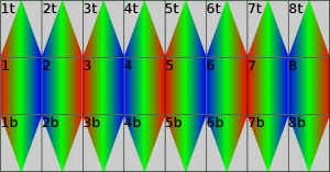
FOV of sub-cameras in Eyesis4π, colors show relative time of the pixel acquisition (from red to blue). Same colors designate simultaneous capture.
Image mask is used to specify which parts of the sensor provide useful data, sensors covering areas around zenith and nadir acquire only triangular segments of the full sensor rectangular pixel array as shown on the picture to the left.
This earlier article explains why using only 50% of the area of those sensors is not a waste but helps to avoid stitching problems caused by fast movement of the camera visible on some high-resolution footage from car-mounted panoramic cameras that use sensors with electronic rolling shutter similar to Eyesis.
Rolling shutter can still cause image distortions in Eyesis but such design guarantees that there will be no duplication or even worse – gaps in the areas where images from different sensors are merged together. When the imagery is used for just rendering panoramas, those residual distortions are not visible (unless the camera was shaken really violently during image capturing). If the same image sets are intended for the photogrammetric applications the rolling shutter effect has to be dealt with to keep the total error in subpixel range, comparable with that of the static camera calibration. Such correction relies on measuring the camera egomotion with the embedded inertial measurement unit and applying camera position/orientation at the moment when each pixel was acquired to the static pixel mapping.
Leave a Reply