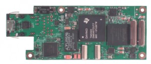
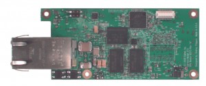
10373 power up OK


So far – so good, after installing most of the components I tried to power up the board. No smoke, power supply voltages (at least those that do not need software to be turned on) seem to be correct, none of the components are hot.
Next step was to connect USB cable to the programming port – there is a cp2103 bridge chip on the board that is connected to the serial port on TMS320DM6467 – port that can be used to boot the system while the flash memory is empty.
When I just started design with this Texas Instruments chip the datasheet was showing network boot mode (similar to Axis ETRAX we used in all our previous cameras) but later that mode disappeared from the documentation (probably TI ran out of the ROM space) so we had to use another way to program the system so it would be both
- safe from “bricking” caused by interruption of the firmware update process (or just plain software bug – our products are designed for development, so bugs are likely) and
- the firmware installation/upgrade would not require any special hardware connections, especially those that require opening the camera case.
The USB connection seemed nice – it is commonly used for the firmware installation, uses regular cables and the port can be used as a system/debugging console during normal operation.
I selected a small (5mm x 5mm) Silicon Labs CP2103 converter as it has additional general purpose I/O pins that can be used to switch between boot modes and generate reset signal for the CPU. This chip seemed to be widely used and to have standard Linux drivers. I was not so sure about those extra GPIO pins support, but noticed that Silicon Labs have some mention of the Linux software, so I’ve purchased their evaluation board to be able to experiment with that software without doing it on an actual board. But I never tried it until the time came to connect the 10373 board. So I opened the evaluation board box, connected it to a computer and – noticed, that there is no support for the extra pins in the regular driver that I’ve got with Ubuntu 9.10. And the driver provided by the manufacturer did not compile with the kernel I’ve got. So I had to spend half of the day figuring out how those drivers work and how to make one that will work on my computer.
That combined driver (I ported only GPIO control from Silicon Labs driver to the one provided with the system) eventually worked and I was able to turn on/off four LEDs on the evaluation board. It required some guesswork and testing as I could not find any documentation on the internal registers and which bits control setting of the GPIO pins – only their API description that assumes usage of some binary-only *.DLL files that may probably work with WINE.
Anyway – I have now a working solution – modified driver and a small application that issues ioctl calls to control GPIO pins. That part also seems to work with 10373, but that is as far as I could go before actually coding for the new processor. And that promises to bring a lot of fun 🙂
Leave a Reply