Elphel next camera – sample configuration
With all three of the new boards for the NC393 series cameras assembled (but only partially tested) it is now possible to connect them with the existent components and show some possible configurations. Main applications of Elphel cameras are scientific research, system prototyping, proofs of concepts designs – areas that routinely require unique configurations, and this new camera series will continue tradition of high modularity.
The camera boards look nothing like Lego blocks, but nevertheless they can zip together in different ways allowing to make new systems with minimal additional hardware. Elphel new design values our prior work (hardware development is still expensive) and provides compatibility with the existent modules, simultaneously enabling new features that were not previously possible, The most obvious example – sensor interface. The 10393 board is designed to accommodate our existent sensor front ends, custom flex cables of different lengths and shapes. That will help us to reduce the transition period to the new camera so we can focus on the high performance system board and port portions of the software and FPGA code, code that is already proven to work.
The same camera sensor ports will allow us to use multi-lane serial sensor connections needed for the modern high speed and high resolution devices, but we will work on this only after the first part will be done and we will be able to replace our current systems with the new ones. Implementation of the serial sensor connection has some challenges for us because the used protocols are not open and we have to rely only on the pieces of the available information and some reverse-engineering and research. It is not the most fun work to do, but being an Open Hardware/ Free Software company we will not provide our users with semi-open documentation. Our users will always be able to rebuild all the binaries from the source code – same binaries from the same code we have access ourselves. The only NDA Elphel ever signed was with Kodak – that sensor NDA had clear expiration time, so at the moment we planned to start distributing our products (and so the source documentation) we were not be bound by it anymore.
Sample configuration illustrated below combines the new and existent modules, the later have links to the design documentation on Elphel wiki. It is not so for the new boards (10393, 10385, 10389) – no circuit diagrams, parts lists or PCB layouts are publicly available when this post is being written. Hardware errors are usually much more expensive to fix, and we do not want somebody to duplicate our hardware “bugs” until we consider our products (“binaries”) to be good enough to go to our users. So while we set up public Git repository when we start software development, we publish our hardware documentation simultaneously with the start of the product distribution – together with “binaries”, not ahead of them.
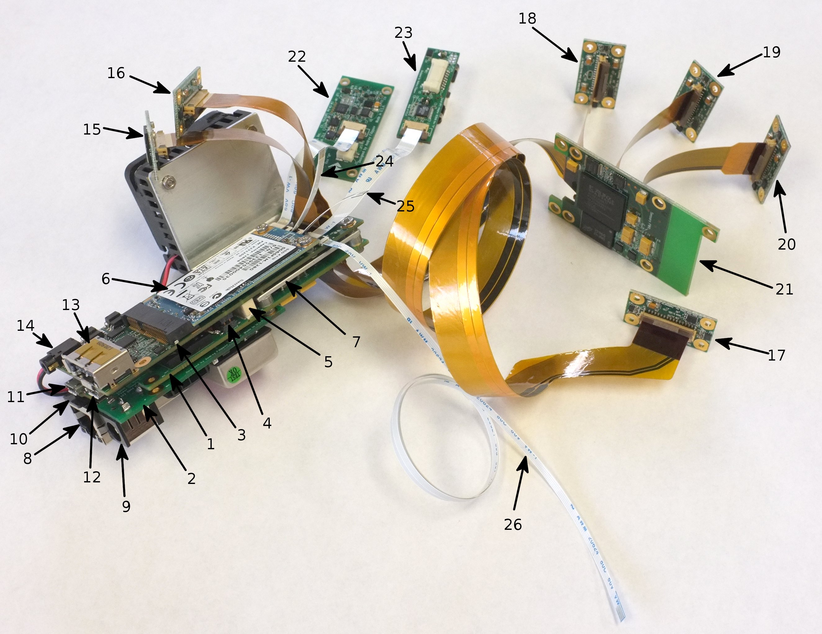
Sample configuration of the electronic modules of Elphel NC393 camera family
- 1 – 10393 Multisensor camera system board based on Xilinx Zynq 7030 SoC.
- 2 – 10385 Power supply board
- 3 – 10389 Interface board
- 4 – Inter-board power distribution: 6-pin (3 circuits) header on the 10385, receptacles on both 10393 and 10389
- 5 – Inter-board signal connector: 40 pins (USB, SATA, GPIO)
- 6 – mSATA SSD card
- 7 – Processor heat sink (temporary). Production cameras will have custom heat spreader to transfer CPU/FPGA generated heat to the camera aluminum body or other heat sinks in multicamera systems
- 8 – Ethernet (GigE) jack, РоЕ-compatible
- 9 – DC power input (9-36V or 18-72V depending on application)
- 10 – Memory card (can be used to boot the system for cold firmware update)
- 11 – Micro USB B connector for system serial console with GPIO signals to select boot mode and generate system reset. Mounted on the 10393 system board
- 12 – Micro USB A host connector for communication with external memory and I/O devices. Mounted on the 10389 interface board.
- 13 – USB A/eSATA combo connector. eSATA port will be used for interfacing external storage devices (HDD, SSD) and downloading data from the camera internal SSD to the host computer. USB portion of the connector can provide power to the external device through the same cable as SATA data.
- 14 – 2.5mm audio type connector for external synchronization input and output (opto-isolated and directly coupled)
- 15,16,17 – directly connected sensor front ends. Compatible with the current 5MPix 10338 (shown) and other parallel data output sensors, programmable interface voltage. With the controlled impedance cables same ports will allow using up to 9 differential lanes plus I2C and 2 extra control signals.
- 18,19,20 – sensor front ends connected through 21 – 10359 multiplexer that allows simultaneous acquisition of images from up to 3 sensors into on-board SDRAM and then transferring them to the system board. In the future we will develop a faster multiplexer supporting serial links to the sensors and/or the system.
- 22 – 103695 – IMU adapter board, or other "granddaughter" extension board connected to the 10389 interface (daughter) board. Two 10-pin connectors provide 3.3V and 5.0V power, USB and 4 GPIO connected to the FPGA pads through high speed voltage level shifters
- 23 – 103696 – Serial GPS adapter board with 1pps input, uses another "granddaughter" port.
- 24,25,26 – Inter-camera synchronization (daisy chain connection) for the systems with multiple camera boards located in the same enclosure, similar to the current Elphel Eyesis4pi cameras
The setup shown above is a sort of mockup – while all the components are real, we do not yet have software to run it, even to test it. So there is no sense in powering up such a system – nothing will happen. And there is a lot to be done before we will be able even to completely test the new hardware and prepare and release revision “A” of each of the prototyped boards. We plan to be ready by the middle of 2014.
Leave a Reply