Elphel-Eyesis-4π preassembly stage
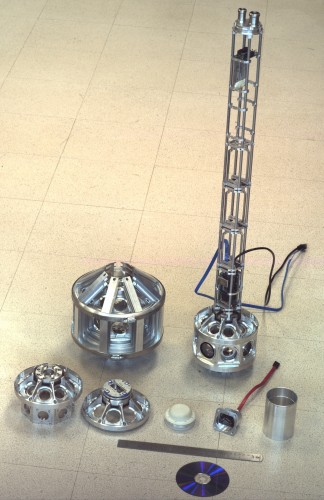
| We have finally received the parts for Elphel-Eyesis-4π camera and started assembling them hoping that all will fit together as we planned. And for the most part they do, which seems a bit like magic to us: you design the camera on the computer in a 3D CAD program, make a long list of parts it will consist of and then a couple months later it all turns into physical object, not just a virtual 3D design.
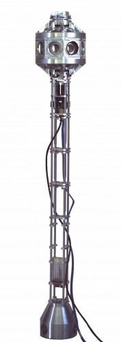
Of course some of the parts will need minor modifications – some are due to mistakes made by us, and some are manufacturing problems. But none of them were significant enough to prevent us from assembling the first 3 prototypes, that will be 100% operational spherical panorama cameras. Elphel-Eyesis-4π is the second generation Panoramic Imaging System by Elphel Inc. It is able to capture high-resolution images in full 360 degrees and create 4π (in steridians) spherical panoramas at a high frame rate. The actual recording device consists of a weatherproof camera head that contains the image sensor front-ends and lenses in spherical distribution to cover the entire 360 degree area. The rest of the electronic components as well as the SSDs for data storage are contained inside the camera pole. Elphel-Eyesis-4π covers a full sphere. 24 sensors (8 in horizontal array, 8 pointing at +30 to + 90 degree (zenith) and 8 pointing at -30 to -90 degree (nadir) ensure a uniform high resolution distribution over the entire covered area. A new Internal Measurement Unit (IMU) mounted at the top of the camera pole provides high resolution 3D position and orientation of the camera. |
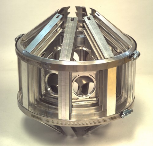
| The main parts of the camera are the head and the pole. Inside the head there’s the optical part consisting of the external Head Enclosure with interchangeable UV protection filters to prevent physical damage of the internal parts and keep the lenses clean. The internal part of the head holds the sensor-lens modules.
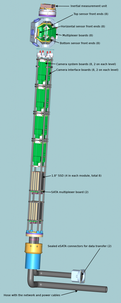
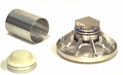
The GPS receiver and the Inertial Measurement Unit (IMU) are mounted on the top of the camera head. The IMU’s platform sits on rubber spacers (blue colored on Fig. 4) acting like dampers to reduce noise in acceleration and angular speed measurements. The GPS is placed above the IMU and is protected with an additional plastic cover. The camera pole is designed to be both lightweight and solid support structure at the same time. Inside the weather sealed camera pole there are camera system boards and Solid State Drives (SSDs). Fig.1 and Fig.2 show the inside of the pole. The electronics are placed inside the pole like floors are laid out inside a skyscraper building. There are 4 floors with 2 system boards each (8 total) and 2 more floors with 4 SSDs each (8 total, depending on the configuration). Additional support structures at each “floor” give the pole additional structural stability. Head with Shade: 230mm Diameter by 308mm Height (including IMU and GPS). Camera Pole: 780mm – 1025mm (the longer pole is to include 2 additional camera modules at the bottom of camera pole, for measuring distance to photographed objects). |
Guys, have you got any images to share in the blog taken with the device? Are there any sensors characteristics available to see? I wonder what ISO and aperture characteristics the sensors and the lens have? Sorry if the question sounds silly but can the device be used in the dark conditions?
Also what focal length the sensors have? Is this controllable?
Yes, you are definitely right – we are terribly overdue with the blog updates. Neglecting “release early” requirement. We’ll try to correct this, but i am afraid we’ll not get to this before the SIGGRAPH exhibition in August..