Elphel new camera calibration facility
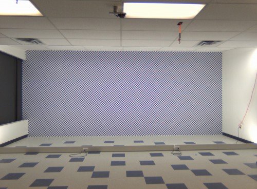
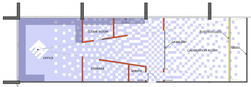
Elphel has moved to a new calibration facility in May 2013. The new office is designed with the calibration room being it’s most important space, expandable when needed to the size of the whole office with the use of wide garage door. Back wall in the new calibration room is covered with the large, 7m x 3m pattern, illuminated with bright fluorescent lights. The length of the room allows to position the calibration machine 7.5 meters away from the pattern. The long space and large pattern will allow to calibrate Eyesis4π positioned far enough from the pattern to be withing depth of field of its lenses focused for infinity, while still keeping wide angular size, preferred for accuracy of measurements.
We already hit the precision limits using the previous, smaller pattern 2.7m x 3.0m. While the software was designed to accommodate for the pattern where each of the nodes had to have individually corrected position (from the flat uniform grid), the process assumed that the 3d coordinates of the nodes do not change between measurements.
The main problem with the old pattern was that the material it was printed on was attached to the wall along the top edge but still had a freedom to slightly move perpendicular to the wall. We noticed that while combining measurements made at different time, as most of our cameras need to be calibrated at several “stations” – positions relative to the target (rotation around 2 axes is performed automatically). We ran calibration during night time to reduce variations caused by vibrations in the building, so next station measurements were performed at different dates. Modified software was able to deal with variations in Z (perpendicular to the surface) direction between station measurements (that actually did help in the overall adjustment of variables), but the shape of the target pattern could change if the temperature in the building was changing during measurements. The PVC material has high thermal expansion, and small expansion in the X,Y directions could cause much higher variations perpendicular when the target is attached to the wall with lower thermal coefficient in multiple points.
Calibration Room
The new space is designed to accommodate various camera calibration procedures.
- First of all we made the pattern as large as possible – it is 7,01m x 3.07m – we even raised the ceiling near the target.
- The target itself is now printed on the film attached to the wall as a wallpaper, so there is no movement relative to the wall, and thermal expansion is defined by a lower coefficient of the drywall. We also provided the air channels inside the wall to make it possible to implement thermal stabilization of the wall.
- The calibration room allows to move camera under test up to 7.5m away from the pattern, the room is separated from the rest of the facility with the wide “garage” door, so changing the lighting conditions outside of the room do not influence calibration.
- Other rooms are designed in such a way that the camera can be moved up to 24 meters from the target (with the garage door open) and have unobstructed view of virtually the full pattern – that may be needed for the long focal length lenses.
Preparing the wall for the target pattern
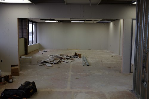
During construction of the new facility we were carefully watching the progress as our temporary space was located just on the next floor and we were mostly concerned about the quality of the target wall. Yes, software can accommodate for the non-flatness of the wall but it is better to start with the good “hardware” – to achieve subpixel precision the software averages correlation over rather large areas of the image (currently 64×64 pixels) so sharp variations will produce different measurements from different distances or viewing angles. When we first measured the wall flatness, we noticed large steps between the gypsum board panels, so the construction people promised to make it level 5 finish and flatten the surface. They put “mud” all over the wall, sanded it and that removed all of the sharp discontinuities on the target surface, but still leaving some smooth ones up to ±3mm as we measured later with the camera.
When the wall was made flat it had to be prepared for application of the self-adhesive vinyl film, so the wall finish will not make it bubble later. Ideally we wanted it to be able to withstand peeling off the film if we’ll have to do that. When we searched Internet about vinyl film application to the painted wall we found that most fresh paint needs some 60(!) days to cure before the film can be applied. So we decided to go with two-component epoxy paint that requires only one week before the film can be applied. When we inspected that epoxy painted wall (the paint was applied with the regular rollers) – it did not look flat. Well, it was just a roller-painted wall, so it had those small bumps and we were concerned that the vinyl film will conform to these bumps, and if it will – the position “noise” will be higher than what cameras can resolve. So we’ve got more epoxy paint and started a long process of wet-sanding and application of the new paint coats. We have compressed air (used to blow during optical and mechanical assembly) so we thought we’ll just spray the paint instead of rolling it to avoid those bumps that were left even after professional work. Unfortunately, without the needed experience in spray-painting, we adjusted pressure too high, and probably as much as a half of our first coat ended somewhere else, but not on the sprayed wall – the paint droplets were too small. Next coat was better, and in several days we had a wall that seemed to be covered with hard plastic laminate, not just painted.
Installing the pattern
Our next concern was – how to install the vinyl film? We wanted to have very good match between the individual panels, as it is not possible to have the target printed on a single piece, maximal width of which is just over 1.5m. We hesitated to order professional installation because for regular applications (like vehicle wraps) such sub-millimeter precision is not required. For the really seamless (compared to the precision of the calibration) we needed better than 0.1mm match, but it is possible to just mask out the grid nodes around the seams and disregard them during calibration data processing, so we planned to get to about 0.5mm match.
We knew people are doing that but still it seemed very difficult to apply 1.5m wide by 3m long “stickers” without wrinkles and bubbles. Web search provided multiple recommendations, but the main thing was to use “wet” method that none of us new before. It involves spraying the wall (and the film on the adhesive side) with “application fluid” (basically water with small addition of soap and alcohol). When the sticky film is applied to the wet surface, the adhesive is temporarily inhibited and it is possible to reposition (slide) the film to achieve required match. Then the water is squeezed away with the squeegee tools, and if done properly, there should be no bubbles left.
Geometric properties of the pattern
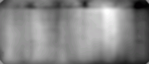
The Z-deviations on Fig. 4 show the wall non-flatness, the gypsum panel borders are still visible (even with “level 5” finish), the horizontal discontinuity near the top is where the wall was extended to accommodate increased ceiling height. Positive Z direction is away from the camera, so lighter areas are concave areas on the wall and darker are bumps extending out from the wall.
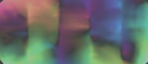
Fig.5. illustrates mismatch and stretching of the vinyl panels application. Red/green color difference corresponds to the horizontal shift, while blue/green – the vertical one.
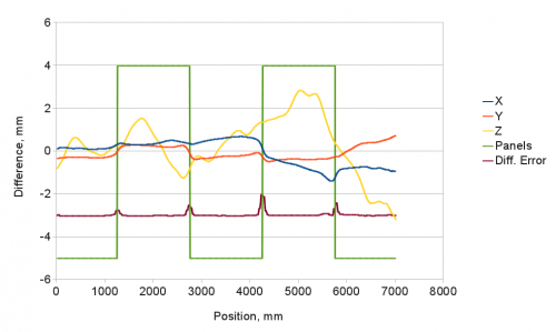
Figure 6. contains a horizontal profile at the half-height and provides numerical values of the deviations. Diff. Error plot indicates areas around panel boundaries that should be avoided during reprojection errors minimization and measuring point spread functions (PSF) for aberration correction.
Illuminating the target pattern
We use the same pattern for different parts of the camera calibration. Correction of aberrations and distortions does not impose strict requirements on the illumination of the pattern, but we use the same images to measure (and compensate) lens vignetting and color variations of the camera sensitivity caused among other reasons by the multilayer infrared cutoff filter and angular variations of the pixel color sensitivity. This method works for low-frequency part of the flat field correction and does not deal with the pixel fixed-pattern noise that, if present should be corrected by other means.
Acquiring thousands of images made by different channels of the camera and capturing the same target, it is possible to perform simultaneous relative photometric calibration of the pattern and the sensors, provided that each element of the pattern preserves the same brightness for each image where it is captured. This may be true when the target is observed from the same point, but when we calibrate Eyesis4π camera with 2 sensors attached far from the other ones, and these sensors travel significantly when capturing the target, this assumption does not hold. The same pattern element has different brightness depending on the lens position when the image is acquired. This is because even matte pattern material is not perfectly diffusive, there is some specular (reflective) component.
In the earlier setup we used photographic lamps with large umbrellas, but these umbrellas were still small when placed at a distance that they were out of the camera view. Specular component was still visible when the diffusive part was subtracted. When designing the new calibration target we decided to use bright linear fluorescent lamps along the floor and the ceiling and keep them spatially compact without any diffusers or umbrellas, we only used mirrors behind the lamps to effectively double the output. Such light source was expected to produce specular reflections on the target, but these reflections occupy just a small portion of the target surface, the rest of it is close to be pure diffusive. That allowed us to locate positions of the specular reflections for each camera station/viewpoint by subtracting the average (between all stations/viewpoints) pattern brightness from each individual station/view of the pattern and then masking out this areas of the pattern during flat-field calculations.
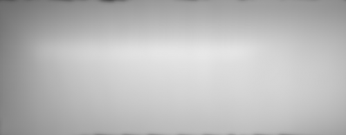
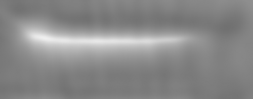
Images on Fig. 7-10 were made for camera station 2 – 3.3m from the target and 1.55m to the right of the target center, that caused lamp reflections to be shifted to the left. View 0 (Fig. 7-8) correspond to the camera head, which is the center of rotations. View 1 (Fig. 9-10) is captured by the camera 2 bottom sensors mounted 820 mm below the camera head, so they were moving significantly between the images – that caused visible curvature on the top lamps reflection.
Virtual tour of Elphel calibration facility
You may walk through our calibration facility using our WebGL viewer/editor. The images were captured with newly calibrated Eyesis4π camera, there is no 3-d parallax correction – these are just raw panoramas stitched for infinity and most close objects are out of depth-of-field of the lenses. Hope you’ll still enjoy this snapshot of the new facility were we plan to develop and precisely calibrate many new cameras.


Leave a Reply