I will not have to learn SystemVerilog
Or at least larger (verification) part of it – interfaces, packages and a few other synthesizable features are very useful to reduce size of Verilog code and make it easier to maintain. We now are able to run production target system Python code with Cocotb simulation over BSD sockets.
Client-server simulation of NC393 with Cocotb
Contents
Previous workflow
Before switching to Cocotb our FPGA-related workflow involved:
- Creating RTL design code
- Writing Verilog tests
- Running simulations
- Synthesizing and creating bitfile
- Re-writing test code to run on the target system in Python
- Developing kernel drivers to support the FPGA functionality
- Developing applications that access FPGA functionality through the kernel drivers
Of course the steps are not that linear, there are hundreds of loops between steps 1 and 3 (editing RTL source after finding errors at step 3), almost as many from 5 to 1 (when the problems reveal themselves during hardware testing) but few are noticed only at step 6 or 7. Steps 2, 5, 6+7 involve a gross violation of DRY principle, especially the first two. The last steps sufficiently differ from step 5 as their purpose is different – while Python tests are made to reveal the potential problems including infrequent conditions, drivers only use a subset of functionality and try to “hide” problems – perform recovering actions to maintain operation of the device after abnormal condition occurs.
We already tried to mitigate these problems – significant part of the design flexibility is achieved through parametrized modules. Parameters are used to define register map and register bit fields – they are one of the most frequently modified when new functionality is added. Python code in the camera is able to read and process Verilog parameters include files when running on the target system, and while generating C header files for the kernel drivers, so here DRY principle stands. Changes in any parameters definitions in Verilog files will be automatically propagated to both Python and C code.
But it is definitely not enough. Steps 2 and 5 may involve tens of thousands lines of code and large part of the Python code is virtually a literal translation from the Verilog original. All our FPGA-based systems (and likely it is true for most other applications) involve symbiotic operation of the FPGA and some general purpose processor. In Xilinx Zynq they are on the same chip, in our earlier designs they were connected on the PCB. Most of the volume of the Verilog test code is the simulation of the CPU running some code. This code interacts with the rest of the design through the writes/reads of the memory-mapped control/status registers as well as the system memory when FPGA is a master sending/receiving data over DMA.
This is one of the reasons I hesitated to learn verification functionality of SystemVerilog. There are tons of computer programming languages that may be a better fit to simulate program activity of the CPU (this is what they do naturally). Currently most convenient for bringing the new hardware to life seems to be Python, so I was interested in trying Cocotb. If I new it is that easy I would probably start earlier, but having rather large volume of the existing Verilog code for testing I was postponing the switch.
Trying Cocotb
Two weeks ago I gave it a try. First I prepared the instruments – integrated Cocotb into VDT, made sure that Eclipse console output is clickable for the simulator reported problems, simulator output as well as for the errors in Python code and the source links in Cocotb logs. I used the Cocotb version of the JPEG encoder that has the Python code for simulation – just added configuration options for VDT and fixed the code to reduce number of warning markers that VDT generated. Here is the version that can be imported as Eclipse+VDT project.
Converting x393 camera project to Cocotb simulation
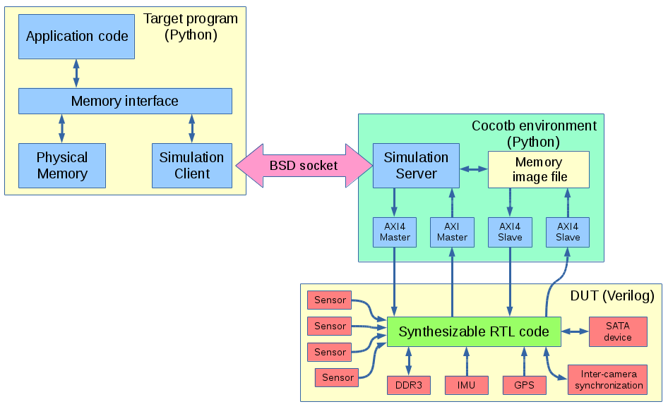
Next was to convert simulation of our x393 camera project to use Cocotb. For that I was looking not just to replace Verilog test code with Python, but to use the same Python program that we already have running on the target hardware for simulation. The program already had a “dry run” option for development on a host computer, that part had to be modified to access simulator. I needed some way to effectively isolate the Python code that is linked to the simulator and the code of the target system, and BSD sockets provide a good match that. One part of the program that uses Cocotb modules and is subject to special requirement to the Python coroutines to work for simulation – it plays a role of the server. The other part (linked to the target system program) replaces memory accesses, sends the request parameters over the socket connection, and waits for the response from the server. The only other than memory access commands that are currently implemented are “finish” (to complete simulation and analyze the results in wave viewer – GtkWave), “flush” (flush file writes – similar to cache flushes on a real hardware) and interruptible (by the simulated system interrupt outputs) wait for specified time. Simulation time is frozen between requests from the client, so the target system has to specifically let the simulated system run for certain time (or until it will generate an interrupt).
Simulation client
Below is the example of modification to the target code memory write (full source). X393_CLIENT is True: branch is for old dry run (NOP) mode, second one (elif not X393_CLIENT is None:) is for the simulation server and the last one accesses real memory over /dev/mem.
|
165 166 167 168 169 170 171 172 173 174 175 176 177 178 179 180 181 182 183 184 185 186 187 188 189 190 |
def write_mem (self,addr, data,quiet=1): """ Write 32-bit word to physical memory @param addr - physical byte address @param data - 32-bit data to write @param quiet - reduce output """ if X393_CLIENT is True: print ("simulated: write_mem(0x%x,0x%x)"%(addr,data)) return elif not X393_CLIENT is None: if quiet < 1: print ("remote: write_mem(0x%x,0x%x)"%(addr,data)) X393_CLIENT.write(addr, [data]) if quiet < 1: print ("remote: write_mem done" ) return with open("/dev/mem", "r+b") as f: page_addr=addr & (~(self.PAGE_SIZE-1)) page_offs=addr-page_addr mm = self.wrap_mm(f, page_addr) packedData=struct.pack(self.ENDIAN+"L",data) d=struct.unpack(self.ENDIAN+"L",packedData)[0] mm[page_offs:page_offs+4]=packedData if quiet <2: print ("0x%08x <== 0x%08x (%d)"%(addr,d,d)) |
There is not much magic in initializing X393_CLIENT class instance:
|
71 72 73 74 75 76 77 |
print("Creating X393_CLIENT") try: X393_CLIENT= x393Client(host=dry_mode.split(":")[0], port=int(dry_mode.split(":")[1])) print("Created X393_CLIENT") except: X393_CLIENT= True print("Failed to create X393_CLIENT") |
And all the sockets handling code is less than 100 lines (source):
|
165 166 167 168 169 170 171 172 173 174 175 176 177 178 179 180 181 182 183 184 185 186 187 188 189 190 191 192 193 194 195 196 197 198 199 200 201 202 203 204 205 206 207 208 209 210 211 212 213 214 215 216 217 218 219 220 221 222 223 224 225 226 227 228 229 230 231 232 233 234 235 236 237 238 239 240 241 242 243 244 245 246 247 248 249 250 |
import json import socket class SocketCommand(): command=None arguments=None def __init__(self, command=None, arguments=None): # , debug=False): self.command = command self.arguments=arguments def getCommand(self): return self.command def getArgs(self): return self.arguments def getStart(self): return self.command == "start" def getStop(self): return self.command == "stop" def getWrite(self): return self.arguments if self.command == "write" else None def getWait(self): return self.arguments if self.command == "wait" else None def getFlush(self): return self.command == "flush" def getRead(self): return self.arguments if self.command == "read" else None def setStart(self): self.command = "start" def setStop(self): self.command = "stop" def setWrite(self,arguments): self.command = "write" self.arguments=arguments def setWait(self,arguments): # wait irq mask, timeout (ns) self.command = "wait" self.arguments=arguments def setFlush(self): #flush memory file (use when sync_for_* self.command = "flush" def setRead(self,arguments): self.command = "read" self.arguments=arguments def toJSON(self,val=None): if val is None: return json.dumps({"cmd":self.command,"args":self.arguments}) else: return json.dumps(val) def fromJSON(self,jstr): d=json.loads(jstr) try: self.command=d['cmd'] except: self.command=None try: self.arguments=d['args'] except: self.arguments=None class x393Client(): def __init__(self, host='localhost', port=7777): self.PORT = port self.HOST = host # Symbolic name meaning all available interfaces self.cmd= SocketCommand() def communicate(self, snd_str): sock = socket.socket(socket.AF_INET, socket.SOCK_STREAM) sock.connect((self.HOST, self.PORT)) sock.send(snd_str) reply = sock.recv(16384) # limit reply to 16K sock.close() return reply def start(self): self.cmd.setStart() print("start->",self.communicate(self.cmd.toJSON())) def stop(self): self.cmd.setStop() print("stop->",self.communicate(self.cmd.toJSON())) def write(self, address, data): self.cmd.setWrite([address,data]) rslt = self.communicate(self.cmd.toJSON()) def waitIrq(self, irqMask,wait_ns): self.cmd.setWait([irqMask,wait_ns]) rslt = self.communicate(self.cmd.toJSON()) def flush(self): self.cmd.setFlush() def read(self, address): self.cmd.setRead(address) rslt = self.communicate(self.cmd.toJSON()) return json.loads(rslt) |
Simulation server
Server code is larger (it now has 360 lines) but it is rather simple too. It runs in the Cocotb environment (coroutines that yield to simulator have “@cocotb.coroutine” decorations), receives and responds to the commands over the socket. When the command involves writing, it compares requested address to the pre-defined ranges and either sends data over one of the master AXI channels (defined in x393interfaces.py) or writes to the “system memory” – just a file system file with appropriate offset corresponding to the specified address)
|
227 228 229 230 231 232 233 234 235 236 237 238 239 240 241 242 243 244 245 246 247 248 249 250 251 252 253 254 255 256 257 258 259 260 261 262 |
elif self.cmd.getWrite(): ad = self.cmd.getWrite() self.dut._log.debug('Received WRITE, 0x%0x: %s'%(ad[0],hex_list(ad[1]))) if ad[0]in self.RESERVED: if ad[0] == self.INTM_ADDRESS: self.int_mask = ad[1][0] rslt = 0 elif (ad[0] >= self.memlow) and (ad[0] < self.memhigh): addr = ad[0] self._memfile.seek(addr) for data in ad[1]: # currently only single word is supported sdata=struct.pack("<L",data) # little-endian, u32 self._memfile.write(sdata) self.dut._log.debug("Written 'system memory': 0x%08x => 0x%08x"%(data,addr)) addr += 4 rslt = 0 elif(ad[0] >= 0x40000000) and (ad[0] < 0x80000000): rslt = yield self.maxigp0.axi_write(address = ad[0], value = ad[1], byte_enable = None, id = self.writeID, dsize = 2, burst = 1, address_latency = 0, data_latency = 0) self.dut._log.debug('maxigp0.axi_write yielded %s'%(str(rslt))) self.writeID = (self.writeID+1) & self.writeIDMask elif (ad[0] >= 0xc0000000) and (ad[0] < 0xfffffffc): self.ps_sbus.write_reg(ad[0],ad[1][0]) rslt = 0 else: self.dut._log.info('Write address 0x%08x is outside of maxgp0, not yet supported'%(ad[0])) rslt = 0 self.dut._log.info('WRITE 0x%08x <= %s'%(ad[0],hex_list(ad[1], max_items = 4))) self.soc_conn.send(self.cmd.toJSON(rslt)+"\n") self.dut._log.debug('Sent rslt to the socket') |
Similarly read commands acquire data from either AXI read channel or from the same memory image file. Data is sent to this file over the AXI slave interface by the simulated device.
Top Verilog module
The remaining part of the conversion form plain Verilog to Cocotb simulation is the top Verilog file – x393_dut.v. It contains an instance of the actual synthesized module (x393_i) and Verilog simulation modules of the connected peripherals. These modules can also be replaced by Python ones (and some eventually will be), but others, like Micron DDR3 memory model, are easier to use as they are provided by the chip manufacturer.
Python modules can access hierarchical nodes in the design, but to keep things cleaner all the design inputs and outputs are routed to/from the outputs/inputs of the x393_dut module. In the case of Xilinx Zynq that involves connecting internal nodes – Zynq considers CPU interface not as I/O, but as an empty module (PS7) instantiated in the design.
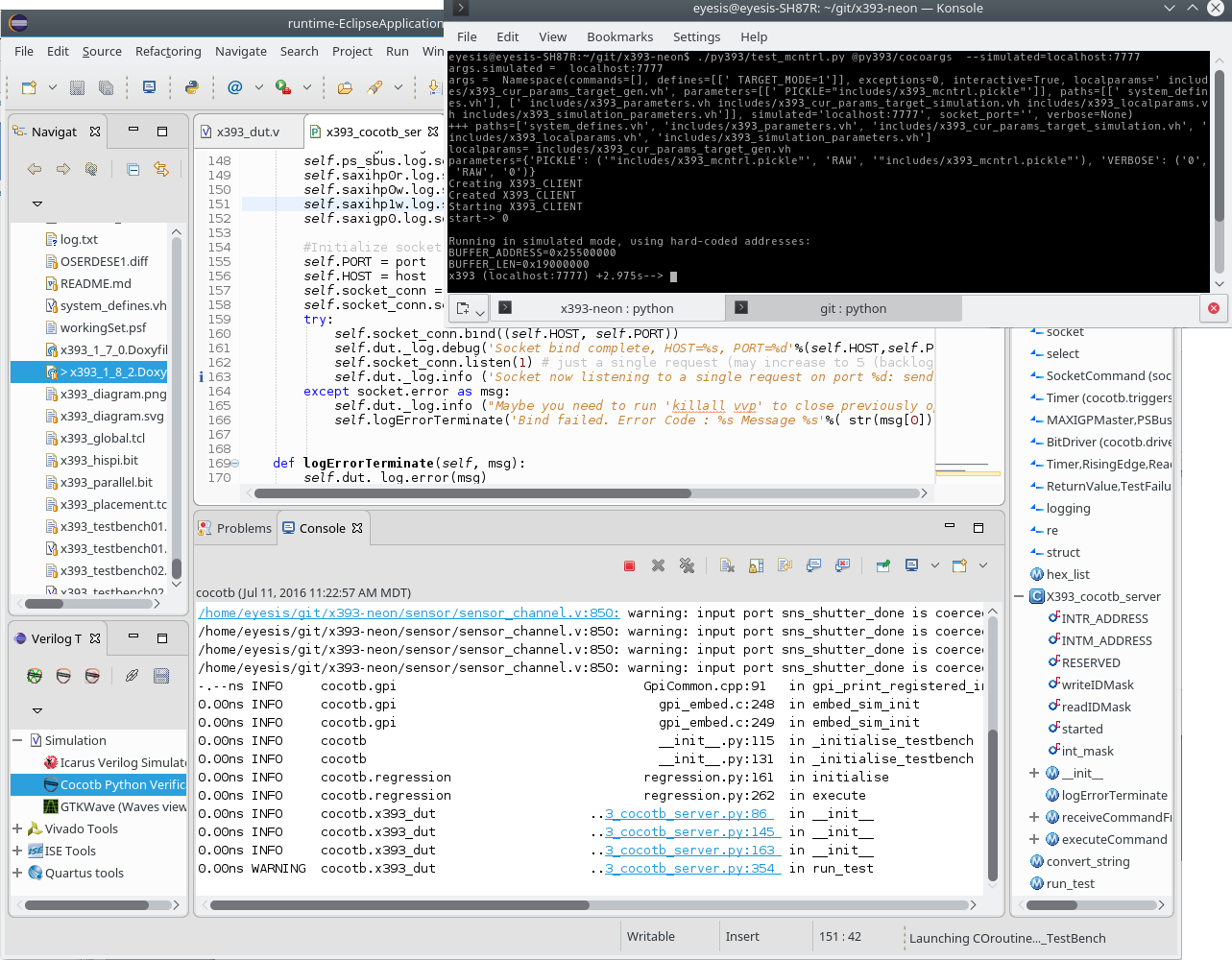
Screenshot of the simulation with client (black console) and server (in Eclipse IDE)
Conclusions
Conversion to Python simulation was simple, considering rather large amount of project (Python+Verilog) code – about 100K lines. After preparing the tools it took just one week and now we have the same code running both on the real hardware and in the simulator.
Splitting the simulation into client/server duo makes it easy to use any other programming language on the client side – not just the Python of our choice. Unix sockets provide convenient means for that. Address decoder (which decides what interface to use for the received memory access request) is better to keep on the server (simulator) side of the socket connection, not on the client. This minimizes changes to the target code and the server is playing the role of the memory-mapped system bus, behaves as the real hardware does.
Are there any performance penalties compared to all-Verilog simulation? None visible in our designs. Simulation (and Icarus Verilog is a single-threaded application) is the most time-consuming part – for our application it is about 8,000,000 times slower than the modeled hardware. Useful simulations (all-Verilog) for the camera runs for 15-40 minutes with tiny 64×32 pixel images. If we ran normal set of 14 MPix frames it would take about a week for the first images to appear at the output. Same Python code on the target runs for a fraction of a second, so even as the simulator is stopped while Python runs, combined execution time does not noticeably change for the Python+Verilog vs. all-Verilog mode. It would be nice to try to use Verilator in addition to Icarus. While it is not a real Verilog simulator (it can not handle ‘bx and ‘bz values, just ‘0’ and ‘1’) it is much faster.
[…] Verilog Simulation with cocotb […]